Limited disassembly of a 1980 IC 196

I must have been tired last night when I was trying to measure c to c on that rod. :mad2: I slipped a digit somewhere, that's why I ask to confirm. Anyway, a recheck and you are right of course. Plugging that 6.75" in, I get: 6.35 dynamic, 8.51 w/5 lbs. Boost, and 9.82 w/7 lbs. Boost. Using 64 degrees abdc. What is not clear to me in the data point they are asking, is "degrees @ 0.050" + 15 degrees". I pulled 64 degrees from my grind sheet, and assumed that was when the valve was closed, not almost closed. :confused5:

so with this "better" data, still looking ok for 91 octane and pull out any unwanted boost by retarding timing?
 
I'll go with that. I was looking over my megajolt datalog and timing map for when I ran my corvair a few times above 7 lbs. (once to 9.2). I usually ran 89 or 91 octane, and iirc, compression had to have been not more than 8:1 or so (it was 0.060" over but I put the thicker shims under the jugs to compensate. "rule of thumb" for that engine brought me back to about 8:1. It had the late hemi turbo chambers). I never detonated that I was aware of and the car is still out there being flogged by its current owner. At the higher "potential" manifold pressures I dialed in 16 degrees total advance (or that's what was left after retarding), but I'll have to check to see if it ever got that low. For starters, I'm going to "map" using the stock 196 curve and use 32 degrees max mechanical, and guesstimate vacuum advance under light loading using the vacuum advance range in the specs. Not hard to do. Then I superimpose retardation pretty much as you state for boost.

I know this engine isn't a 152 and its hp and torque curve will be different. In looking at the 152t hp and torque curves superimposed over the n/a curves, max hp is still around 3900 and max torque is shifted about 800 rpm up the scale (2400 rpm and 3200, respectively). The n/a 196 favors max torque at 2,000 rpm, and my uneducated guess is that the boosted max torque will be closer to 3k, but you know better based on what that cam grind will do. This engine May be a stump puller and that's pretty much what I wanted. I was also looking at the b flow boost map and how IH actually pulled off sizing it for a broad power range rather than favoring one end of the scale or the other (looking again at mcginnis' theoretical curves). I agree a more modern turbo and f.I. Is something to shoot for for future tinkering, but for now, an f flow appears to work to about 5 lb and then drops off the map below 60% @ 7 lbs, which isn't acceptable. An e wheel will flow around 70% efficiency and up the scale past 7 lbs. Nicely, and I can moderate the curve and limit boost (again, looking at mcginnis' discussion of acceleration curves) by restricting the carb side. At this time the yh May fit that bill perfectly. I have an f flow turbine, so if I'm only playing with 4k max, boost should come on a little before 3k and be done by 4k, and not exceed 7 lbs. A good place to start.

Correction: I had earlier mistated that a b flow would work on a 196. No way - no point is to the left of the 60% (choke) line. I'm also thinking that IH broadened the boost curve by choking the intake with that 1904 1-bbl, and giving it that 2 1/2" overkill exhaust system.
 
Last edited:
Robert,
you just never know. When calculating my compression ratio, I used some of your numbers because you had already worked some things out. Today I actually took the time to measure the boot heel in one of my four pistons. The one I just measured was 12 cc - no way it is 10 cc. So now I'm going to do the rest, but it will be likely more of the same. Quite some variability with silvolite, no? I have one of the oem pistons here and am curious to measure that heel. It looks visibly smaller than the silvolite heel. Maybe it's 10cc!

I am also going to calculate the volume of the area within the gasket by using graph paper and the "squares" method and see if I come up with your 9 cc. Wouldn't hurt to see what my gasket yields.

Now here's what I'm thinking. Assuming the 9 cc is close enough for now, and using 10 cc for the heel, and 91cc for the head, that gave me my 8.3 c.r. 8:1 was what was thought to be better. Well, 12 cc in the heel gives me 8.15 based on this rationale: calculations had determined I lacked 4 cc to bring it to 8:1, so now I appear to have an extra 2 cc, I split the difference. Also, that heel is not all that smooth and I'm thinking of cleaning it up and might pick up another 1/2 - 1 cc. Then I'd be down to about 8.1 or a tick less. I am confident in doing this as I have a very precise scale (down to the gram) and will monitor my progress so all my hung piston/rod assemblies weigh the same. Those were balanced to within 1 gram at the balancer. (wow, they weigh about 2,020 grams each!) as any slight weight change is in the heel, it won't affect running balance. And if I didn't have a graduated scale, I dawned on me that I could also estimate volume by using the specific gravity of aluminum. 1 cc water = 1 gram. Dense aluminum has a specific gravity of 2.8, so 2.8 grams aluminum = 1 cc. I'll just monitor the weight change when cleaning things up, then confirm this logic by cc'ing it afterwards.

Then I can clean up the combusion chamber and maybe gain another 1/2 cc. Maybe just cleaning things up will get me to almost 8:1. :yesnod:

a note: if I hadn't decked this thing, the c.r. May have been around 7.75:1
 
Last edited:
Ooops. Pic didn't load first time.
 

Attachments

  • Piston cc (Small).jpg
    Piston cc (Small).jpg
    26.9 KB · Views: 598
Good reason to do one's own measurements.
Error is always part of the process. Either components or method of measurement. Would you like to give us some detail on your method and instruments?

I use two methods one is as seen in the sticky where you likely got my volume(which I trust) where a graduated medical syringe is used to dispense the liquid and one using a hanging graduated cylinder (lab instrument) known as a burrette as the process is so named.
 
Robert,
I don't mind at all. If I am off, then I am off. I am not using a medical syringe (I used them when in the clinical setting in a previous life, and don't always consider them as accurate as lab equipment). My graduated cylinder is simply one from a kit from summit, so it May be "good enough".

Technique:

filled cylinder to 50 cc line (lining up meniscus), using 50/50 water/alcohol, and a drop of red dye.

Using a light smear of white grease (see picture), placed plate onto top of piston, pressed down tight and got a good seal. Carefully poured liquid into teeny hole without spilling any (I have a steady hand) and filled it and tapped it to get air bubbles to come out of hole (was able to tilt piston and it worked out better than expected). When all air was out, and filled just to the hole, the cylinder read 38 cc (again, meniscus against line like the 50 cc line for consistency). Two cc's is actually quite a bit. Only sources of error are a cylinder that's inaccurate (possible), a plate that bowed (it isn't), or possibly an uneven piston top (it's flat), or something leaked out (it didn't), or I spilled some (I didn't). Occam's razor tells me the real possibility is that for whatever reason, the heels in my pistons are actually 12 cc. So I think my results are good. :icon_mrgreen: please let me know what you think.

A few years ago one of my jobs was checking the calculations in shielding plans for those concrete vaults they install those 20 million volt cancer treatment machines into. Did 'em all by hand to ensure the process was correct. Amazing the mistakes you find in automated calculations. The devil is in the details, which will bite you every time. ;)

p.s. I used engineering graph paper and measured the volume of my felpro ic196 head gasket. Comes out to a tick over 8.91 cc, so I think that's very good agreement with your 9 cc.

Post script. Back from out of town trip and holiday. Yesterday cc'd the other three pistons - each is 12 cc. Cc'd one of the oem pistons. 10 cc. As to the difference in the reliefs, which is quite noticeable, I'd venture silvolite increased the volume of the bootheel to compensate for the increase in c.r. That results from oversize pistons. Going from stock 4.125 pistons to 0.060" oversize adds another 1.4 c.I. To each cylinder. My rough calculations indicate that increasing the bootheel's volume by 2 cc drops the c.r. By about 0.15 points, basically cancelling the effect.
 
Last edited:
Now that the holidays are over and I have some time to get back to the project...

The business of ending up with a higher c.r. Than desirable for one of the main objectives of rebuilding the engine (turbo), I obsessed with reducing it from 8.3:1 to 8:1 :icon_sweatdrop: the problem was due to my inexperience and getting the horse before the cart with respect to getting those pistons mounted and not checking volumes and such first. Hopefully won't make that Mistake again!

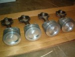
Here's the logic behind what I've done to fix that problem. I discussed the situation with the shop that balanced the rotating assembly. They offered to remove the pistons, mill out the relief to my specifications, then reinstall the pistons. They claimed a very high success rate in doing this without ruining the wrist pin fit ("you aren't the first one to get it backwards" was what he told me), but no guarantees, of course. So when I had to make that decision, I shrank back and thought better of it. But since it was clear that removing the same amount of material from the top of each piston would not upset the balance already put into each piston/rod assembly, I figured if I could very carefully grind out the necessary material, confirmed through weight removed as opposed to volume removed, then that could be a path forward. Today I finished doing just that. Here are the specs:

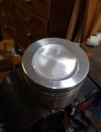
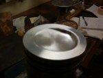
1 cc water = 1 gram. Since dense aluminum has a specific gravity of 2.8, 2.8 grams = 1 cc. So I needed to remove around 5.6 grams aluminum from the top of the piston. Consulting with silvolite catalogue's cross section of the piston, it was obvious the crown was thinnest at the bottom of the bootheel. So I would polish out the bootheel and extend the "d" to roughly complete the circle. Again, the machine shop would have done just this except with using an end mill, my guess was that careful grinding would be the same thing.

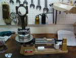
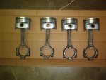
I have a triple-beam scale accurate to 0.1 gram. I first weighed each complete assembly (minus rings and bearings). The four piston/rod assemblies were within 0.4 grams of each other. My goal was to maintain this spread, and possibly improve upon it.

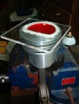
I selected the lightest assembly (1,961.0 grams) and using wide masking tape, taped it all up to keep out the grit. I weighed that assembly (adds about 9 grams!), and then began lightly grinding away at the heel's arc with a 3/4" drum sander mounted in the drill press, then switched to a 2" rotoloc disc (180 grit, iirc). Since the top of each piston has very fine concentric lines, it was easy to follow the desired contour. What resulted was actually a very nicely polished surface, much better than what was in the heel to begin with. Of course I'd grind, weigh, grind, weigh, grind, weigh, then do another, compare, weigh, compare, etc. Until I got them all down to about the same weights (within 0.3 gram), and paying particular attention to the pairs that would go up and down together. Got those to 0.2 g or better. When I finished, I cc'd the reliefs and confirmed they were now 14cc instead of the original 12cc. I now calculate a c.r. Of about 8.03:1. Close enough, no? This was a very time consuming process and took a whole day.
 
Last edited:
Trying to add pictures again!
 

Attachments

  • 196 piston relief (Small).jpg
    196 piston relief (Small).jpg
    21.6 KB · Views: 430
  • 196 piston relief 2 (Small).jpg
    196 piston relief 2 (Small).jpg
    30.8 KB · Views: 437
  • Piston on scale (Small).jpg
    Piston on scale (Small).jpg
    56.6 KB · Views: 455
  • Piston set (Small).jpg
    Piston set (Small).jpg
    46.1 KB · Views: 423
  • Piston set reliefs (Small).jpg
    Piston set reliefs (Small).jpg
    47.3 KB · Views: 441
Begun reassembly today. Washed block one last time, ran brushes through galleries one last time (still looked clean), wiped down and blew off all surfaces. Ditto with crankshaft.

Wiped cylinder bores and lifter bores with 30 wt break-in oil.

Cleaned bearing shells, installed dry against webs and caps, clevite assembly lube on journals, arp thread lube on threads, torqued main caps down to 80 ft. Lbs. In three stages. Smacked ends of crank with bfh (block of wood between hammer and ends, of course), between torquings.

Crankshaft turns about as easily as it can (weighs what, 75 lbs?) with a simple twist of the hand. No binding I can tell. :gringrin:

bagged it all up, maybe piston/rod assemblies later this week.
 
Glad you have her going back together.

I like to use feeler gauges to set the thrust bearing main. When you first set in the crank in to the loaded saddles measure the thrust clearance with a fg and leave it is with the one thinner in your set.if it measures .007 place the .006 fg in the other side and place the cap and bearing snug the bolts and make sure you can still move things. May tap things a bit fore and aft. Once you clamp the bearing shells they are pretty embedded. Trying to slip them by beating the crank back and forth can burr things up.

Just my screwy way of doing things :winky:

that being said if you have the right end play leave her be.
 
I did the whacking while it was at about 30 ft. Lbs., not after. I have 0.003" endplay and it turns *easily*. Don't know what else I'd do. Maybe tomorrow set the pistons, or the cam. I do need to order the arp studs.
 
Robert,
you got me to thinking (again). I loosened the cap with the thrust surfaces, and reinstalled, then began fitting feeler gauges to see what thickness would fit best, about 0.006", straddling the parting surface between the two shells. Left two feelers in place to keep cap from shifting, then torqued it down. Endplay now 0.005-0.006", so my original attempt obviously had the cap shifted a tad. :icon_eek:

installed camshaft today. Need to measure endplay, but as it's the original camshaft and thrust washer, not expecting anything has changed.

This week I hope to degree that camshaft....stand by to tell me how that new grind ended up!
 
.005 is about the best you can get. Glad you got it ligned up nice, the .003 bugged me. :out:
I use the same technique to align the rod caps. One fg across each parting line. Also takes the torque loads while torquing the rod caps. The oem IH rods have no means to accomplish this like a sleave or dowel.
 
I posted the following question over on the bp forum, with mixed results: since no new oil pumps are available, I put a kit in the pump. Not happy with the way it turns, slight catching as it goes round. Might be a slight burr or the sharp edges of the gears, I don't know. Endplay is about that 0.003" needed. I did lightly run that end plate back and forth across fine sandpaper to get the surface a bit smoother first. So I put in the old gears, which looked pretty much like the new gears save for some slight/light circular lines (scoring). They turn nicely, but duh. I'm of a mind to just let it be. My '75 Scout manual says the spring should be 2.500" (no, not a typo) but the spring in it and the new one are around 2.250". Thoughts on what to do about that, if anything?

It seems to me the solution to truly rebuilding these would be to accurately bore out that shaft hole and press in a suitable steel bushing so the gear with the shaft would turn in a true hole, with snug clearance, and be supported along the bushing's length.

If I had a mill/drill, I'd almost give it a shot.
 
The spring's free length has little to nothing to do with oil pressure unless it is an oem part and oem rate. The load @ the installed dim is the data point you need to worry about.
The manual gives both a compressed length and load. Iirc

as for pump clearances, a pump is a calibrated leak and all parts have a running clearance. They are not designed to be set up at 0.000 or a slip/ press fit. They need to be able to pass debris and crap that May end up in the pan to the filter. Drop the pump in a bucket of clean oil and drive it with a power drill. That will burnish any high spots you May be feeling.
 
Last edited:
Found some nicks on the end edges of a couple of teeth. Lightly filed those off with a fine file, then put the gears in in different locations (shifted teeth) till I found a good running spot. Now it seems pretty good and I agree just run it now and let it bed in. Both gears have the same number of teeth so the same teeth will wear in over time. I just don't like the wear in the shaft hole (probably par for the course), but that's got to be what we got to work with.

Just got off the phone with arp, will fax in the dimensions for my studs tomorrow. Those are the final parts to get, but final reassembly must wait until after vacation now. Do that in two weeks. Btw, gaps on my top two rings measures 0.019". Good to go?
 
Yeeehaw! Just ordered the head studs from arp. Unfortunately one stud is on backorder until mid-August, but the rest were off the shelf pieces.

With the studs, I now have all the parts.
 
All but one of the arp studs arrived (lower left rear when viewed from the side of the engine). Put those in for a dry fit-up, and used the one stock bolt, plus had a spare head gasket and wanted to check the clearance of that fire ring to the defect previously described. Torqued it all down to 80 lbs. Just to get it all seated, then removed the gasket. The outer edge of the fire ring is right at the edge of the defect, but doesn't appear that it actually encroached on it. I suppose it's good to go.... Compressed thickness @ 80 lbs. Is 0.050", but in the final torquing will go to 105 lbs., so it will probably be a tick less than that. One of the studs has 1/4" of excess threads (lower right, which is towards the front), no biggie. Two of the upper studs seem to be a thread short wrt the nut. Cause for concern? I'm using the arp washers which are significantly thicker than the oem washers. If those particular washers were half their thickness (but still thicker than the oems) I can see where the full length of thread would engage.

Edit: seeing that the head gasket will have a compressed thickness around 0.048", plugging that into the calculator gives me a c.r. Of 7.95.

Maybe this weekend I'll get a chance to install pistons, then degree the cam. Getting closer!
 
Last edited:
Back
Top