Limited disassembly of a 1980 IC 196

Now that vacation is over and got things under control at the day job.

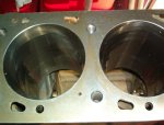
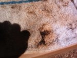
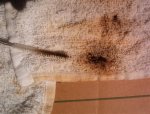
In spite of what anyone says, no one can be responsible to ensure engine cleanliness unless you do it yourself. Machine shop tanked engine 2x and said "absolutely clean, don't need to do any further cleaning", so I took delivery of block in a big plastic bag. Couple of days ago removed all the oil galley plugs, and the little one at the front end that caps the tappet galley. Well, well, well. An inch of crud and grit lurking behind that one. Also found a deposit of crud up inside the block; a wipe with the finger brought it back covered in black soot. Ironically the machine shop advised me to clean the crank 'cause the balancers don't do a good job of that. In running the brush into the holes, found some oil passages had significant grit in them. So a word to the wise. Don't take anyone's word for it. :hand:

got the head disassembled on Sunday and will hopefully grind out the smog humps this weekend, then get it over to the machine shop. The backside of intake valve #2 had a 1/4" thick deposit of carbon on it. Talk about a restriction. Two of the exhaust valves were wobbly. How does one assess the exhaust valve rotators?

The 0.020" over moly rings arrived, courtesy of northern auto parts.
 

Attachments

  • Crud in passage (Small).jpg
    Crud in passage (Small).jpg
    72.2 KB · Views: 426
  • Crud in passage 2 (Small).jpg
    Crud in passage 2 (Small).jpg
    56 KB · Views: 420
Last edited:
Some questions about grinding out the smog bumps. My head is drilled and tapped for a smog air rail, which had been removed sometime in the distant past. The #3 cylinder had a factory plug installed (still in there and I can't get it out) 'cause later rails only used three tubes. So last night it was fairly easy to grind the humps on those three down to "flush". So there are now three oval holes in the port's roof. I guess that's ok, that won't affect exhaust flow? Tonight I'm going to grind down the one with the factory plug in it and I think I'll end up with that port roof being fairly well flush with no real hole 'cause that plug projects into the port and will be ground down flush.

So should I get three factory plugs and grind them flush and install to try to have port roofs fairly flush, or try to remove the plug I am about to grind, and just have regular short plugs and port roofs with the holes?
 
I discovered I have three of the long plugs, so why not get the fourth and grind them flush. Since I'm committed now, of course no going back if one needed to install an air rail. The meat those teeny air tubes get wedged against, is gone. I was surprised how quickly a bump can be ground down, a little over 10 minutes. So next week off the head goes to get new valves, etc.
 
I'll be taking this head to the machine shop next week. I did follow some of the threads here about valves and guides. Are the silicon bronze guides hard to find, or is that something my shop should know about? If not, where would I direct him? My guess is that at a minimum I'll be buying all new exhaust guides and valves. We'll see where the intakes shake out.
 
Head dropped off at the machine shop today. I specified that I wanted the silicone bronze guides in the 0.415" size and stressed that they were available. After looking further into their books, they found a listing that matched the specs I found elsewhere here. So....as long as they can actually get them. He's going to tank the head and do all the measurements, but in the end, I want to replace all the exhaust parts, at a minimum. A fair bit of wobbling on at least two of them. Not that anal about the intakes. He did mention that it was his practice to set the exhausts up at 0.002", so that's good. Getting closer to getting this thing put together. :icon_wink:
 
.002 is a bit tight for a truck engine but so long as he hones not just reams the guide id to a nice finish .002 is ok.
 
I guess I'm a little confused here. Looking over Jesse b.'s thread from a couple of years back plus what's been posted here earlier, I thought 0.002" would be ok, and that's what the shop was inclined to do. As he hasn't done this yet I can call him Monday and tell him 0.0025" for the exhaust if that's safer. Intakes should be 0.0015 - 0.002"?

I did get a call from him Friday afternoon about the head. It needs to be surfaced slightly (good - it will be flat after that), and he's getting those correct silicon bronze exhaust guides and all new exhaust valves. One intake valve needed to be replaced, too. So I have one chance to have him do it however it is recommended here to do. I think Jesse b and I are using the same shop but having different experiences.

Washed the block yesterday. I don't care how great they say those machine shop washers work or how many times through they ran it. I brushed crud out of the oil galleries that would have gone straight to my bearings.
 
Head is done. Now the assembly can begin. I do have the factory manual sitting here, but just a couple points to clarify.

1) main and rod bearing shells. Should those be absolutely clean on the backside when pressing into their respective cavities, or should there be a thin coating of oil between the shells and the block webs and rods?
2) threads for rod bolts and main cap bolts get oiled. I read this as a "yes", just confirming.

Got the rings. Will set the top ring gap to 0.020"

had contacted arp a few months ago and the guy there never followed up on matching up some studs, so I need to call them again.
 
#1 is a no. The web and shell back should be dry to aid in staying still.

#2 use a moly assembly grease or anti seize on the threads and under the bolt head and washer.
 
Robert,
got the head back. They had to surface it but I didn't ask how much they took off to clean it up (call them later today). I plan on getting a small piece of lucite and a graduated cylinder because the only way I can know exactly the combustion chamber volume is to cc it. Looking at your previous post on this topic, my estimate is:

49.33 ci (I'm at 0.020" over or 4.145") or 808.51 cc
assume your 10 cc valve relief volume
assume your 9 cc head gasket volume
my silvolites "should" bring me to a zero deck but will confirm when I actually install a piston. So assuming all of the above (808.51 + 9 + 10 + 85) we have 912.51 divided by 104 = 8.77 cr. Of course the variable will be my true "deck" and true combustion chamber volume. But that's the ballpark. Aside from only adding 0.020" over to the cylinder's volume, I'm surprised that the ratio appears to be this high.
 
434514C2 head (Small).jpg

IC 196Head (Small).jpg

Piston mock up 2 (Small).jpgbeginning the reassembly and reassement process. Got the cylinder head back (196/392 434514c2) and cc:'d it. 91 cc, and that's after having a few thou planed off to clean up the surface. Mocked up one of the new silv-o-lite pistons. It sits 0.033" below the deck. My calculations using 0.020" over, the 91 cc head, and assumed 10 cc relief and 9 cc felpro head gasket, and 7.33 vol for "in the hole", I get a c.r. Of 7.9. Zero decking (or real close as others here have done) bring it in around 8.25 - 8.3. I don't mind dragging this block back to the machinist to trim off 0.025 or so if a quench effect will offset any benefit of running a lower c.r. When boosted. Curious how much can be planed off one of these blocks?

The crank polished up nice. Plastigauging the mains brings them all in around 0.0025", spins real nice by hand. The one con rod bearing I've gauged came in a tad bigger than 0.0015", so hoping the rest are as good.
 
Last edited:
Block back from machinist, had him take off 0.030", so when the pistons get installed, they May be about 0.003" in the hole if my initial measurements were correct. But there's a little hole in the deck (communicates with coolant space) that I never noticed before, about the 5 o'clock position for hole #3 (just left of the lower bolt hole). In Robert's picture of the ic392, right bank, I see what looks like a dimple, so that's what got planed off and exposed. As long as it is well this side of the gasket's compression band, it should be ok....?
 

Attachments

  • Pinhole (Small).jpg
    Pinhole (Small).jpg
    43.4 KB · Views: 583
block back from machinist, had him take off 0.030", so when the pistons get installed, they May be about 0.003" in the hole if my initial measurements were correct. But there's a little hole in the deck (communicates with coolant space) that I never noticed before, about the 5 o'clock position for hole #3 (just left of the lower bolt hole). In Robert's picture of the ic392, right bank, I see what looks like a dimple, so that's what got planed off and exposed. As long as it is well this side of the gasket's compression band, it should be ok....?

No problem at all. So long as it is outside of the fire ring it is fine..... As you said.
I see those on 99% of these blocks. Some are hardley noticable others are small holes. I think they are remnants of wire used to hold the sand casting shoe together or line it up.............. I am guessing. :eek:
 
Robert,
thanks for the reply. I have a head gasket on order so I'll fit it up when it comes in to confirm. Seeing that hole gave me one sleepless night.

Looks like I'll be kissing 8.3:1 for a c.r., if my quench space comes in around 0.043" or thereabouts. I'm trusting this was the right move.
 
Robert,
thanks for the reply. I have a head gasket on order so I'll fit it up when it comes in to confirm. Seeing that hole gave me one sleepless night.

Looks like I'll be kissing 8.3:1 for a c.r., if my quench space comes in around 0.043" or thereabouts. I'm trusting this was the right move.

Your cr of 8.3 seems low.
 
Low as in should be higher, or low as in I made a math error? (always possible and I welcome having those errors pointed out :d). So here are my assumptions:

808.51 cc (my calculation of 4.145 bore x 3.656 stroke)
9 cc (gasket volume)
10 cc (relief volume)
decking the block actually removes some swept volume, so the 7.33 cc assumed at being 0.033" in the hole becomes about 0.7 cc @ 0.003" in the hole via simple ratio'ing
91 cc for my combustion chamber (ic 196/392 head casting 434514c2, directly measured).

808.51 + 9 + 10 + 0.7 + 91 = 919.21. 919.21 divided by 110.7 (91 + 10 + 9 + 0.7) = 8.3.

Since I'll be running some boost, wouldn't even 8.3 be on the high side?
 
So if my 8.3 calculation is essentially good, then is it low, close enough, or high? Of course, it is what it is, but still...
 
Back
Top