Limited disassembly of a 1980 IC 196

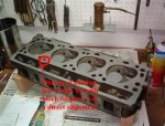
Took the day off to continue assembly. Took me half the day to fuss around and get #1 piston in (had to drive down the mountain to get a different ring compressor but ultimately needed both styles), but it's in. Used 0.006" feelers across the rod cap and torqued it down to 45 ft lbs. Piston and rod assy turn easily. Rod moves squarely back and forth that 0.006" on rod journal and piston pin, so that's a relief. Got the degree wheel in place and have re-established tdc; this evening will begin the degree process to see if it matches the grind sheet.

Interestingly (or maybe not so surprising), the deck isn't square to the top of the piston. Clearance on the intake side is about 0.006" and the outboard side is 0.003". I'll be checking each succeeding piston in turn just because.

By this weekend should have it almost done (except for the head) but still waiting on that arp stud.

Edit:
my degreeing skills aren't the best, but here are some numbers after toiling in the heat. I had some difficulty in getting my dial indicator stabilized. I also think my tdc is probably not better than within 1 degree

from sheet: intake @0.006" 9.78 btdc, I get 11, close is 64 abdc, I get 63;
@0.050,14.95 atdc, I get 15; close is 29.87, I get 29; @ 0.100 it's 30.64 atdc, I get 31, close is 13.04 abdc, I get 12; @ 0.200 it's 63.56, I get about 63.5; close is 2.18 bbdc, I get 4; 0.250 is 92.05 atdc, I get 91.5, close is 48.29 bbdc, I get 48.
Exhaust: 0.006 shows 56.68 bbdc, I get 57, close is 25.55 atdc, I get 25; 0.050 shows 32.57 bbdc, I get 33, close is 10.43, I get 10; 0.100 shows 16.65, I get 17, close shows 27.23, I get 28, 0.250 shows 38.86 abdc, I get 39, close shows 82.86 btdc, I get 84.

As I said, my "precision" with an angle bracket as marker and the cheap summit degree wheel (damn that thing isn't concentric!) leaves something to be desired - if I'm within 1-2 degrees I'd be impressed, but the key measurements seem about there. I can't get the centerline numbers to work and that's got to be a defect in my thinking, or maybe it's 100 degrees and I'm hot and tired.

Tomorrow I'll install the last three pistons.

Getting there!
 
Last edited:
interestingly (or maybe not so surprising), the deck isn't square to the top of the piston. Clearance on the intake side is about 0.006" and the outboard side is 0.003". I'll be checking each succeeding piston in turn just because.

The piston will never be perfectly parallel to the deck. It rocks back and forth a bunch. Using a plastic tool of some kind, you can push it around in the barrel and probably get the piston top ant any angle you desire..

Your cam location looks fine. +/- 2 degrees is really not even noticable.
 
Just got the remaining pistons in. The mental check list: deburr ends of rings, reconfirm (scraper rails are 0.026", spec is max 0.028"), ensure dot is up, ensure moly ring is in top land, rings staggered, backs of bearing shells dry and wiped with acetone, arp thread lube on rod bolt threads and washers. Assembly lube on bearing surfaces. I find that taking my time and going methodically takes around 30 minutes per hole. If the ring compressor cooperates.

Anal as I was about this, I still managed to put one piston in upside down. My first clue was when the rod cap wouldn't line up. My language was creative, but not original.:mad5:

if the cam is good to go, then I'll be a happy camper. Just need that last stud (eta 8/17) before the head can go on, then oil pump, etc. So close now!
 
Major bummer. Began buttoning things up and cycled the pistons. Noticed that on #2 hole that a fine scratch or scuff developed as that piston went down :eek6: so I pulled that piston. If the outboard thrust surface is at 6 oclock, then is was around 7 oclock. It seems there was a burr on the top edge of the piston. I specifically felt round all the pistons for burrs (my fingers are only now recovering from the fine cuts), as I found a couple and dressed them off . But this one got by me. So I pulled out the fine file and a few quick swipes and the burr is gone. Damn!!!!

Wiped the cylinder down. The scuff is faint and visible but isn't detectable with the skin on my fingertip, but is just detectable - barely - via the edge of a finger nail. Sometimes I feel it, sometimes I don't. The rings don't show any scratches in that area.

I'm sure this would be a show-stopper for a professional engine builder, which I am not, and I'm thinking of still proceeding with cleaning the piston up and reinstalling it. Or what - disassemble and take back to the machine shop for a quick pass with the hone?
 
If you can't pick it up with your nail or soft pass of a finger it is less then .0002. Never be an issue. Leave it be I'd say.
Deburr and reassemble.
 
Okay, but I was feeling so good about how it was all going until this.

Question: about how bad does a long scratch have to be before it is a problem? Does the ring move (rotate) enough randomly to obliterate minor defects as it goes up and down, or do they quickly bed in or captured and then lock in to a certain orientation?

Post script: piston out, cleaned, de-burred, hole wiped clean, everything reinstalled. Half the time can't detect any irregularity, so I'll call it marginal....moving on...what it is is what it is.
 
Last edited:
okay, question: about how bad does a long scratch have to be before it is a problem? Does the ring move (rotate) enough randomly to obliterate minor defects as it goes up and down, or do they quickly bed in or captured and then lock in to a certain orientation?

Tough question but if one considers that the honing cross hatch (.0005 deep depending) can and does last for 100,000+ miles in a well maintained engine, don't plan on it wearing away anytime soon. It will play absolutly no part in increasing oil consumption or loss in compression. Most of the cylinder wall texture will fill in with varnish or carbon deposits over time and become perfectly smooth as the rings only touch the high spots.

I'm of the opinion that rings for the most part don't rotate.... Much. Pulling down low mileage engines I've not witnessed gaps lining. But they must move some.

Don't loose any sleep over it Mark.
 
Next relevant questions to address. I have the boat style rockers, and got replacement welsh plugs from sss, so I'll be popping out the old and cleaning up the interior. How much wear on the pads of those rockers is acceptable (the spot that rubs against the valve stem)? Mine don't have distinct, sharp boundaries but shiny spots that are a detectable, what, depression or area of wear. I recently had an opportunity to pick up a spare boat-style rocker assy at pnp, and was considering combining the two for a 9-stand version, why not. Useful or not?

Then when the rocker assy is installed, have to address the level of pre-load on the new lifters and see how much has been altered with 1) that reground camshaft and 2) decking the block 0.030". I'm shooting for about a minimum 0.050" preload, right? I do believe these are the final details in buttoning up this engine and plopping it back in the truck.

At least the shiny new red paint looks purdy!
 
How much wear on the pads of those rockers is acceptable (the spot that rubs against the valve stem)? Mine don't have distinct, sharp boundaries but shiny spots that are a detectable, what, depression or area of wear. I recently had an opportunity to pick up a spare boat-style rocker assy at pnp, and was considering combining the two for a 9-stand version, why not. Useful or not?

Have them resurfaced or replace them if there is a depression. The valve rotation is important and if the valve it being pushed only around the stem tip things are not happy.

I think the 5 stand is robust enough but 9 is stronger. If you have the holes in the head over the intake runners plug them with the 4 other stands.

Then when the rocker assy is installed, have to address the level of pre-load on the new lifters and see how much has been altered with 1) that reground camshaft and 2) decking the block 0.030". I'm shooting for about a minimum 0.050" preload, right? I do believe these are the final details in buttoning up this engine and plopping it back in the truck.
At least the shiny new red paint looks purdy!

The lifters will take more then .125" of plunger repositioning(preload) and still function perfectly. By the same token they work fine with as little as .025" of pleload.
If you wanted an optimum range .025"-.075". Sweat below .025and above .125".
 
IM002101.jpg

IM002102.jpg

IM002104.jpg

IM002105.jpg

IM002110.jpg

IM002111.jpg

IM002100.jpgpictures of putting on the head. Cleaned both deck and head surfaces with xylol. That truly degreases and cleans metal. Put head gasket on, printed side up (as it came out of the package) interestingly, I followed arp's guidelines for measuring studs. The studs on the bottom row, at the ends, are taller than necessary (bottom left by at least 1/2", bottom right at least 1/4"), but as everything clears the nuts, oh well. On the top row, the three center studs were "short" wrt the nuts by a thread or so. Arp said I could back off the studs up to 1/8", so I backed those off 1/2 turn, and voila - studs now engage all of the nut's threads. Installed studs after using their grease. I torqued everything down in four stages and waited between stages to let the gasket compress (30, 60, 90, 105#). Arp said 110#, but I quit at 105#. Head gasket squeezed down to 0.039", so I have a quench space of around 0.043 - 0.044". The bottom right bolt hole with the "iffy" threads (earlier in my thread I had that horribly corroded and crudded up bolt) held - didn't feel anything going soft. :grin grin:

also, pics of the pieces of my dummy drive before gluing the cap on with jb weld. As the upper bushing I installed was an oilite style bushing, I think it will lubricate well from engine oil vapors. I drilled a vent hole alongside the seam between the bushing and aluminum body so the cavity above the bushing vents into the engine. The clearance with the shaft and bushing was so close that it trapped air in the cap.

Edit: since that one stud is unnecessarily tall, I'm thinking of just ordering another stud of the same length as the other bottom three. Should be no problem just removing it and torquing the new one down to 105#?
 
Last edited:
Some notes on my use of arp studs. In case anyone else considers using studs on an ic 196/392, here's what I ended up with, and here's additional information to guide one in going this route. Stock bolts are 1/2"x13 of various lengths.

I used the arp order sheet where you enter dimensions of the depth of threaded holes, head thickness, etc. I carefully probed the holes and made measurements with a micrometer. When my order arrived, I discovered there were two studs that didn't seem to follow the script - the end studs in the lower row. So here are the part numbers, and what I learned. Orientation is facing the head from the passenger's side.

Top row of five studs: ar5.250 (1/2 x 5.25" long)
bottom row, center three: ar3.620 (1/2 x 3.620" long).
Bottom row, left corner. While my measurements had arp send me a 4.060" long stud, it was about 1/2" too long when installed (see picture in post immediately preceding this one). I substituted this with another ar3.620, which ends up with the same installed height as the other three. Go figure. So in reality, get four ar3.620" studs.
Bottom row, right corner: ar5.000 (1/2 x 5.000" long). You need one of these.
Nuts: 200-8607 (1/2 h&m hex nut) (you can also get the twelve point nuts but they are something like $3 each vs 78 cents each) you need 10 of whichever you decide
washers: 200-8514 (1/2 id 7/8 od no chamfer), likewise, 10.

My block was decked 0.030", and head was lightly surfaced. I used the felpro composition gasket, which is a nominal 0.051" uncompressed, and after applying the 105# torque, compressed to 0.039". I lubed all threads/washers/undersides of nuts with arp thread lube.

The upper studs were unscrewed about 1/2 turn after being screwed down until they stopped. No torque is applied to the studs otherwise. This was done so the threaded upper portion would would completely engage the nut's threads. This was done at the direction of the arp technical support. I think another alternative is that arp has hardened washers that are thinner. Using these could get you to the same place without needing to back the studs off at all.

The long stud (lower row, right corner) projects above the top of the nut by at least 1/4". If you wanted a neater appearance, perhaps arp has that part number in a slightly shorter length. I'm leaving mine as is.

I was concerned that this long stud would pull out the threads, as the original bolt's threads was solid rust - seems this bolt hole can collect water that dribbles down into the threaded pocket (pictured earlier in this thread). Upon closer inspection, I put that bolt, with washer, in the head and took measurements to see how much thread engagement actually occured with the oem setup. My measurements indicate that that original bolt only engaged 0.6" of the available 1.0" thread length. The arp studs have 1.0" thread length available, so when they are screwed into the block, full engagement occurs (that's reason enough to go with studs!). In this case, if the upper threads were in fact weakened, getting that additional 40% engagement with threads that never really were used, made for solid clamping.

Hope this helps.

All that's needed now to complete reassembly is getting my hands on a serviceable rocker arm shaft. The new boat style rockers arrived yesterday.
 
Last edited:
Thanks to Mike at IHOnly south, I now have a serviceable early shaft that I've put the new boat rockers onto, along with the full compliment of nine stands. So there. Before I put it on, I checked over the top of the head one more time....looking down the oil feed hole that is in the head next the the stand third from the left, I see it dead ends into the deck! I thought the oil feed hole would communicate straight down into that hole in the deck and on down into the cam area. Is it offset from this hole? Where does the oil come from?? It doesn't seem there'd be enough flow through a hole in the head gasket if it is.... :crazy:

edit: installed the rocker assembly to check for preload on the first two lifters. While at tdc (assume base circle), and using a probe (nail bent 90 degrees and ground down to 0.075" thickness), it fits between the circlip and top of plunger with clearance, so I guesstimate around 0.085" preload, which is great. So it seems that my decking the block 0.030" and whatever was removed when the cam was ground, either cancelled out or wasn't a problem to begin with. Whatever.

Also, the third stand from the right wouldn't bolt down as the arp washer has a slightly larger od than the original washer. Solution is the clearance the stand's "web" in that area, and voila!
 
Last edited:
This photo (your's but marked up) should clarify the oil passage question.....
 

Attachments

  • rocker assy oil transfer port.JPG
    rocker assy oil transfer port.JPG
    63.1 KB · Views: 599
Picture worth 1,000 words. I had overlooked that small pocket, which makes perfect sense.

Now heading to the garage to finish putting in the lifters, pushrods and rocker arm assembly.

I've welded up a small bracket for the pick-up coil for my (eventual) crank-fire system. I saw where a Chevy guy created a 36-1 trigger wheel from a pulley sheave (geee, just like IH pulley sheaves that we stack up) and that solved a host of fabbing problems. He cut the teeth himself with a grinder, but I think I'll cast around for a shop to put the sheave in an indexing head and mill them. I discovered if you take the sheave with the lesser offset and turn it around and put it next to the hub, it will put the teeth-to-be out of the way and you can nestle the pick-up coil against the timing gear cover, between the timing Mark boss and the water pump intake. Post pics a bit later. I have machined a large aluminum cap to bolt onto the sheave stack to secure the outermost sheave which drives the p/s pump. Will also drill and tap four more holes in the hub for added strength.
 
Pics of the crank fire mock-up. This makes the pulley stack thicker by the thickness of the metal in the pulley, and puts the outermost pulley just beyond the hub. I'm machining an aluminum disc to pilot into this pulley and sandwich/clamp it all to the face of the hub, thus solidly mounting it.

The rearmost of the pulley's "v" gets a notch cut every 5 degrees to make a tooth 5 degrees wide (notch is also 5 degrees wide); the 9th tooth clockwise (90 degrees) from the pickup coil gets removed which becomes the reference point so the computer knows where tdc is located on a four-banger. That's why it's called a "36-1" wheel. I'll run the engine on a distributor until I get it running and broken in a little bit, then this will be already in place when I switch it over to the megavolt.
[
attach]17521[/attach]

IM002119.jpg

IM002121.jpg

IM002120.jpg
 

Attachments

  • IM002118.jpg
    IM002118.jpg
    46 KB · Views: 389
Last edited:
Robert,
a couple of observations. I bought a new torque wrench because I dropped the other one (it was about 12 years old and infrequently used). Wouldn't trust it after that. Since the engine's been sitting for a couple of weeks, right before buttoning it up tonight I retorqued things to the same settings just to be sure. Head studs took, to my way of thinking, a bunch of additional torquing to get them all to the 105# I had previously used. Could that be just from the head gasket relaxing or taking its *set*, or chalk it up to the new wrench? Likewise, the mains and rod caps took additional torquing to get back to the 80 lb/45 lb, respectively. I would guess somewhat around 5 lbs or so. Anyway, I'm not going to sweat it. I replaced all the pushrods just because some appeared iffy. The local napa and oreilly's both sell the sealed power rp3133s, but neither had more than four, so I bought batches from each. One set of four had the ball ends (like in "balls") and the other batch had the ball ends more like bullet ends, but same part numbers and same identical lengths. So I installed them in alternate pairs, just because. Cam lobes are really smeared in comp cams assembly lube, as are the pushrod ends, new rocker arms, and on the tips of the valves. Got some oil into the lifters (I see elsewhere that you don't prefer that technique - is that so there's less pressure on the lobes for the first few minutes?).

Anyway, I've checked and double-checked all knowable bolts, studs, and pipe plugs, checked all side/end play, and frankly there's nothing left to do but put the rear cam plate on and the rear seal, and the tin. Even with everything installed, the crank can be turned by hand with no binding or real resistance. It feels great. And get my pulley machined into a 36-1 wheel. That's it - looks like it's pretty much a done deal. Unfortunately for me will be in socal off and on the next month on business, so it's a matter of finding time to get'er back in. :rita: can't wait to fire it up!
 
First I'd ask what make the new tw is. The hf ones are shit pardon my french and only good for a hammer or breaker bar.

I regularly verify my click tw with a high quality beam tw (my standard). I use a craftsman micro torque (name ?) and it has been stable for 15 years. Only once did I have to calibrate it.

Second when you were re torquing things, did you back them up 1/4 turn before tightening? If so I can understand a difference in end position especially with the proper moly applied properly. Amazing what a difference in clamping loads it makes.

If not it would seem you have a big discrepancy between the calibration of your tw's.

My deal on prepriming lifters is that while adjusting the preload a hydraulically solid first class lifter can remain solid for a while and hold a valve open creating a piston to valve clearance issue when you reposition the crank to set the others. Just how I do it and not usually an issue on a lopo engine.
Proper preoiling will oil things and soon as it fires things should be quiet real quick. Assembly lube on all valve train wear points. Will protect things fine.
 
Bought it at napa. No, I didn't back off the nuts first, just applied torque to see what would happen. ????

I have an old craftsman beam style I bought decades ago and have kept safe . maybe I should compare them ! I know that I won't trust the old wrench after having dropped it . or maybe I should shag on down to my machine shop and have them compare wrenchs - would be worth the cost . engine still on the stand so if I have to remove the rocker arm assy (again), it's still not a big deal .

I did rotate the engine a few cycles slowly, so the lifters did have some opportunity to bleed down .

getting sooooo close!
 
If you have good a beam tw put a socket that will connect to the 1/2" square on it and reference 100ft/lb on the beam wrench with the other (clicker) to 100ft/lb.. Put the clicker in a holding fixture and see where the two are.
 
My pulley-converted-into-trigger wheel has just arrived. I took the standard 4-banger hub and drilled and tapped four more mounting holes for added clamping and will put in two roll pins to make the pulley stack very rigid as the outermost pulley will run the p/s pump and is unsupported. This weekend is set aside to finalize the mounting, and after I get the allen head bolts (drilled for safety wire) that will bolt the pulleys to the hub.

IM002134.jpg

IM002135.jpg

IM002137.jpg

IM002138.jpg
 
Last edited:
Back
Top