Limited disassembly of a 1980 IC 196

Last weekend I attended the IH Sierra Fall Rallye. Someone told me that they wished I would just finish up this project. All in good natured fun, of course. I whole-heartedly agree, but unfortunately life isn't like that. Today I got to an important part - fabbing up the exhaust system. I have purchased mandrel-bent parts (two 90 degrees, two 45 degrees) two couplings, 18" of that flexible stuff, and 3' of straight. All 2 1/2" o.d. So the Scout went up on the stands and I got the head pipe dropped but haven't been able to wiggle loose the pipe from all the crimped connections, which brings me to another detail. I purchased a v-band connector kit, and am going to weld one side to the cat inlet, the other to the new portion that will snake its way up into the engine compartment and to the turbo outlet. Or vice-versa. This way, when (if) I need to put the original back on for smog, it minimizes the hassles mostly of removing welded or clamped parts. Later I'll weld a spare v-ring on the original head pipe…

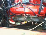
after putting the Scout up on stands, I removed the heater, the 2-bolt exhaust manifold, and belts for the alternator so it can swing out of the way as it needs to clear the end of the 3-bolt manifold. Since I am keeping the cat, I also need to keep the air manifold. I cut one down to three legs (well, the '79 and '80s used 3 legs anyway) and shifted it rearward to clear the cast-iron elbow. As you can see, it all still bolts up!

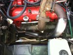
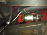
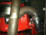
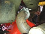
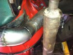
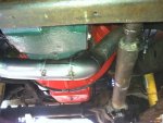
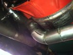
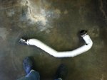
After bolting up the wedge, manifold, elbow, and turbo turbine housing, I begin the fitment of bits and pieces. I cut down the corvair outlet elbow which has a special end for the packing-style gasket to accept a 90 degree mandrel bend, and then added a 45 degree bend. All is now tacked and ready to weld. I will add another 45 degree portion to what you see, which will clear the starter solenoid - barely - and the go between the frame and that bulge in the corner of the block by the bell housing. More clearance around it than I thought it would have. A rough fit-up shows me that I need another 45 bend and the judicious use of some of that flex tubing to make it all work and not look too crappy.

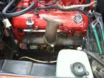
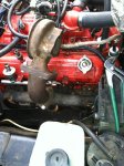
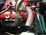
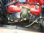
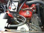
First pic is a shot of the stock 196 engine compartment - quite busy. Second pic is with the wedge added, and third shows the elbow to mount the turbo. I apologize for how dirty my engine looks. I have the ubiquitous leaks that are so difficult to eliminate, even on a relative fresh engine.
IMG_0922.jpg

IMG_0923.jpg

IMG_0924.jpg
 
Last edited:
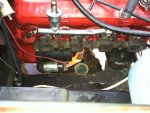
Here is the elbow with the turbine housing, then with the corvair turbo stub, and then after cutting in a new piece. I'm hoping I'll have clearance for a sanden compressor, as I do need my a/c.
IMG_0925.jpg

IMG_0926.jpg

IMG_0928.jpg
 
Last edited:
I read that you are leaving the cat in the system. The biggest most important number the determine turbo efficiency is perssure dif across the turbine. The cat can kill that. Anything you can do that reduces down stream back pressure adds to the energy remaining to drive the turbine.
Also the turbo will reduce egts below the turbine. That could allow fouling of the cat.
 
Robert,
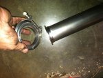
I hadn't considered the egt downstream...so the turbine could remove enough heat so the cat won't light off. That's reason enough to remove it. I fortunately made more progress yesterday in welding additional downstream tubing but haven't gotten as far as the cat. At this stage, having removed the entire system, which was actually quite simple, it will be easy to weld the v-ring to the inlet to the muffler and have a straight pipe back to that. And it would be easy to weld a matching ring to the cat's outlet and thus have a modular approach to when I need to switch it back. This could all be done in a day. What makes removing/replacing exhaust parts such a b*tch is having either welded joints or clamped joints to remove. Yesterday I needed a sawzall to remove parts, but won't in the future. As it stands now, the turbine's outlet pipe goes neatly down to that space formed between the frame rail, the body, and the corner of the block just behind the starter, just like it was designed for it. There it ends and I will fashion a piece that will slip over this end (clamp), then under the bell housing before turning a 90 and heading straight back to the muffler.

About the back pressure. I am leaving the stock 2 1/4" muffler and tail pipe in place and I really don't believe that will prove unusually restrictive, especially since the carb has a 1 1/2" throat. Since I don't have a wastegate, this should suffice to keep boost under control for the time being. I've envisioned duplicating the ancient cast iron elbow in steel and tapping it for a wastegate flange. With wastegate control, there would be other carb possibilities.
 
Love those v-rings (commonly known as band clamps). Have a 258 with a header that goes into a y before the muffler. Had a band clamp installed in front of the muffler. Allows you to drop out the section of pipe between the muffler and header flanges in minutes, making it easier to work on transmissions, clutch linkage, pull engines, etc.
 
By any name they are wonderful items. I'm tempted to add one to that joint where the "down pipe" meets the "crossing under the bell housing" pipe. :icon_mrgreen: my welding skills improved a lot yesterday. One of the "joints" ground down and looks almost like an oem weld. The next one is sound, but not so pretty. :icon_eek: I do need to add a wide-band sensor bung to where that new portion outside the turbine housing just begins.
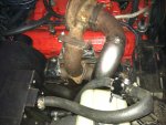
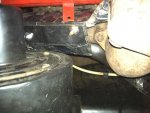
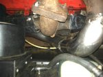
Hondo's comment about easing accessibility makes it well worth the effort and expense.

Edit: a goofy historical tidbit is that the "marman clamp" was invented by herbert marx in the 30s. Herbert marx is better known by his stage name, zeppo marx. He was one of the marx brothers!
 
Last edited:
Took a few minutes to confirm something that really needed confirmation before proceeding: will the heater box and fan motor clear the manifolding????

The answer is a resounding yes! With room to spare. I was particularly sweating that fan motor poking sideways near the valve cover. No worries. After removing the air injection tubes, I put that super rare heat shield in place. Refer back to earlier pics in this thread as to what that looks like. It folds under the manifold to protect the starter, and forms a sort of box. I should move the washer bottle forward to where the jack (which I don't have) would mount, to protect it from its present proximity to the exhaust pipe. I plan on wrapping the pipe in a high-temp fibrous wrap I got from mcmaster-carr and used on my corvair's piping to block excess heat in the engine compartment, and also wrapping the fuel line and vent line that runs on the inside of the inner fender. I also need to solder ells on the heater core's piping to point upward and reroute the heater hoses. This all should look very tidy when I'm done.IMG_0930.jpg

IMG_0932.jpg

IMG_0936.jpg
 
Last edited:
This stuff.

Edit: silly me. I think I figured out why some posts show the pics and other just show the file names and you need to click to open. If you write the text and then add the pics and the close it out and submit, you get names. If you begin with inserting pics, and then finish the text and submit, you get a pic.

Update: hope to finish the exhaust system by next weekend. The past two days has been an agony of cutting/fitting/repeating getting the tubing around the block and front driveshaft. Discovered that the left-over piece - with mandrel curves - of that early corvair turbo pipe, will be adaptable and "fill the bill" as it tucks between that boss on the bell housing (with the large threaded hole used for other applications, but unused on the Scout) and the shaft. The challenge will be cutting a series of 15 degree wedges and weld them into a curve to go around a corner at the bottom. Pics to follow and explain… I have found the welder settings that work for the 18 gauge tubing, so life is good.
 

Attachments

  • Collar material (2).jpg
    Collar material (2).jpg
    30.2 KB · Views: 389
Last edited:
"turning the corner", literally. Got this done this evening outside before the light failed….

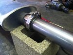
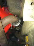
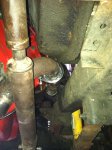
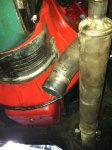
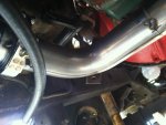
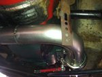
I tack welded a short stub to the v-band ring, then installed it. Took the old corvair exhaust section and positioned it to get maximum clearance between it and the top of the front driveshaft - about 2 1/2 to 3 "fingers" which is what, 2" or so? That's the best I can do for now, except that I plan on flattening the pipe in this area by either the application of the bfh, or better, since my skills are improving, welding in a flatter section. My suspension would have to bottom before the shaft would actually hit, I think. Anyway, I contoured a welding rod to determine how to section additional wedges to turn the corner at the bottom and head up and to the left to meet the pipe that then runs back to the muffler.IMG_0945.jpg

IMG_0946.jpg

IMG_0947.jpg

IMG_0948.jpg
 
Last edited:
I'm really tiring of fabbing this exhaust system, but I am coming in for a landing. Today I finished cutting/fitting/tacking/re-cutting/re-fitting/re-tacking, etc. It's pretty much done except for finishing the welds themselves and cleaning it all up. My welds are crappy, but lots of grinding will smooth things out and make it presentable. The old corvair pipe burned through in places (thin spots where it was stretched when it was bent), but I've been able to patch it.

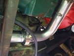
I have barely adequate clearance to the solenoid and have shielding material to place between it and the pipe. Should work. The lowest spot of the pipe - where it crosses under the bell housing, is just at or slightly above, the lowest level of the crossmember, so if I had a skid plate it would still work. It crosses right under the louvered clutch cover, but since I have v-band clamps, if I needed to inspect or adjust the clutch, it is a simple matter to remove that section of pipe! I still need to make brackets to solidly mount the piping around the engine, like the original, so that everything is mounted solidly at the point the piping goes straight back to the muffler. In my case, it will require reinforcing the strap thing hanging from the bolt that secures the clutch cross-tube bracket (has the pivot ball). This was the oem arrangement.IMG_0954.jpg

IMG_0955.jpg

IMG_0956.jpg
 
Last edited:
And these.
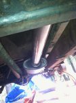
Edit: forgot to mention that the 90 degree transition going straight back isn't quite directly under the clutch linkage, but is close. The original pipe is 2 1/4" diameter and dog-legs closer to the transmission so as to not be under it at all. I wasn't about to add a dog-leg - waaay too much work at this point - but chose to simply shift the pipe over a little bit. The issue is that when you disengage the clutch, the rod in the cab goes down, and at the end of this rod is a yoke engaging one of the bars welded to the clutch relay tube. I first wedged the clutch pedal down and then crawled underneath and confirmed clearance, which is about 2" (visible in img 0957). The pipe itself sets about 1" or so above the transmission crossmember, so I think there's sufficient clearance all around. Of course, the first time I'm on a trail and really have the suspension crossed up will be the real test as to how things clear!IMG_0957.jpg

IMG_0961.jpg

IMG_0963.jpg
 
Last edited:
And the last. These are looking from front to rear. I think there is plenty of clearance for the front drive shaft even if I don't flatten the pipe in that area. Which I still plan on doing.
 
Oops. Pics didn't load for some reason. Here they are. I still need to weld in the bung for the 02 sensor. Just an added note here. I bought two marman clamps from the specialty exhaust place in rancho cordova. They were pricey. I found the same size (but not the same vendor) clamp in jegs, much cheaper, and with free shipping. This clamp was of slightly heavier construction and more than adequate, but clunkier, for lack of a better word, to clamp up than the pricier ones.IMG_0964.jpg

IMG_0965.jpg
 
Last edited:
Question for Robert k. I am going to drill a hole and weld in the 02 bung. If you reference the picture looking down on the turbo and first few feet of tubing (shows the old stub and new piece grafted in), where would it be best drilled? In the old section, or further down in the new? Or maybe it won't matter if it's within the first few feet. Thinking of exhaust gas temps here, but if the 02 is heated, it shouldn't matter in any case? My first inclination was in the new portion, where it is vertical and goes down. Sensor would be pointing rearward but clear the cast iron elbow.
 
I just saw this Mark, sorry.
If you want to measure afr like a wide band sensor, it really should be as close as possible to the collector of the header. I don't know what effect the turbo will have on the readings. So I would say as close as possible to the turbine housing exit.
 
Last edited:
In the diesel world, egt's are much more accurate when the pyrometer probe is pre turbo. Normally drilled in the exhaust manifold before the collector portion. I know that you aren't using an actual pyro but normally the consensus is 150-200* difference in pre vs post turbo egt's.
 
in the diesel world, egt's are much more accurate when the pyrometer probe is pre turbo. Normally drilled in the exhaust manifold before the collector portion. I know that you aren't using an actual pyro but normally the consensus is 150-200* difference in pre vs post turbo egt's.

Unfortunately it won't be possible to mount it pre-turbo, using the oem parts. I have thought of duplicating the cast iron elbow in steel just so I can drill a hole in the schedule 40 pipe it would take to mount a sensor as well as an outlet for a waste gate. T4 flanges are available commercially, and I think a triangular base flange could also be fabbed fairly easily.

The 3-bolt exhaust manifold used for the 152t is a duplicate of the 2-bolt manifold, except for the flange. It also didn't include the boss included on some manifolds for use with a hot air choke (drilled for that hot-air well the tube fits into). If they had, I would have drilled and tapped it for a sensor, but alas, they never did. So I can't!

Although exhaust gasses flowing through the turbine give up heat energy in the process of spinning the turbine, I hope there's sufficient heat to operate an o2 sensor. Iirc, they need to be heated to about 600 degrees. I believe the sensor is heated, which makes this a moot point, or if not, I'd lose function at idle, but it would work when spun up. That's really the condition I'm putting it in there for in the first place - tuning a/f ratio under boost to ensure I don't run lean.

Edit: Mike, I don't know how hot diesel gasses burn pre-or post, compared to gassers. May not even be an issue, but I do not know if that's so.
 
Last edited:
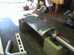
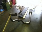
And this. Now that the tacking for positioning is all done, I removed the entire system and reassembled it in the garage so I can finish welding all the seams. These are all the bends needed to clear the frame, starter, block, bell housing, and crossmember. What is this, 15 feet of tubing and muffler?

It's raining so this is a "rainy day" project.
 

Attachments

  • IMG_0967.jpg
    IMG_0967.jpg
    54.5 KB · Views: 404
Got all the welds done on the exhaust piping, even added the bung for the 02 sensor. It's located about a foot or so downstream from the turbo outlet and I'm not worried about it working, as reading about those with the innovate lc-1 (now 2) it works quite well even temporarily placed in the tailpipe, so I don't think this is a thing to stress over.

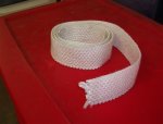
My 2 1/2" wide fiberglass cloth strip - 25' roll - arrived. It's good to 1,000 degrees f. I will wrap the entire length of the pipe from the turbo to the first marman clamp, which is just past the starter.

Today I had planned to properly mount the wedge and 3-bolt manifold, but the 152t hardware is always at the ready "to surprise". How do I explain this….the mst-113 says to use the usual exhaust locking tab washers, except the pocket machined to accept the bolt head is circular and there are no "flats" that the flat bent over part would go against. Scratch that idea. The mst calls out for five 2" long bolts. When bolted up, these are short inside the little ears on the head, you know, the ones that break off now and then. I need all the clamping I can get so I bought 2 1/2" allen head bolts, cut them down to 2 1/8", plus drilled the heads with a 3/32" bit for safety wire. Easy-peasy, actually. I skimmed the copper rtv on both side of the first exhaust gasket and bolted 'er all up with sae flat washers behind the allen bolt heads. Then on went the safety wire. I bought one of those handy safety-wire pliers (those are so cooool) but even so, I need some work on my technique. Oh, and I used anti-seize as some of the threads do come through the little ears and are exposed. One day those May need to be removed.

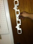
Next step was adding the 3-bolt manifold, which is otherwise identical the the common 2-bolt job, except that it points up. Now, the mst calls for two exhaust manifold gaskets. I thought the one going between the wedge and the manifold would go on just like the other, but to my shock, it can only work by mounting upside down! The manifold is upside down and those little mounting buttons are now up where they must contact the cantilever arms cast into the wedge. And at that, the bent over flange part gets in the way of everything. In short, it's impossible unless you severely modify it by cutting off the flange and notching the areas between the ports and right below the holes for the bolts, as any material in these areas hits against the bolts that mount the wedge to the head in the first place!

At this place in history it is impossible to ask anyone from the assembly line how this little trick was done in a way other than what I'm puzzling out right now. :mad2: in the meantime, you'd want to figure this all out before you skimmed that rtv all over both sides, right? I managed to use xylol to remove it and after cutting away lots of the metal shim exhaust gasket, I'm probably going to need a transfusion when all the bleeding from my fingers eventually stops. Cutting tin is hazardous!
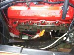
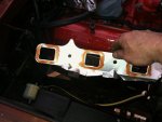
IMG_0971.jpg

IMG_0972.jpg

IMG_0974.jpg
 
Last edited by a moderator:
Wow! Now it is beginning to actually look like a 196t! Seeing today's progress gets me within "drooling distance" of getting this thing done. The main thing now is to cast an adaptor for the side draft carburetor.

Today I bolted up the assembly using the rebuilt turbo and not the "dummy". In doing this over, I would do the following: trim both shim style exhaust manifold gaskets to remove the flange that is present to shield heat from the plug wires. Not needed if one has the original large heat shield, or maybe even if I didn't have it. The gasket closest to the head gets in the way of my plug wires anyway. I still had to cut a chunk out of the flange by #1 plug. I bolted the manifold down to 30 ft. Lbs. And used the oem locking tab washers. I bolted the cast iron elbow to between 30 and 35 ft. Lbs. I customized a g8 bolt (fine) for length and for a castle nut and drilled it for a cotter key. In addition to the other two bolts using flex nuts, I also added the oem lock tabs. I don't want this particular part coming loose.

For now I used flex nuts for mounting the turbo to the elbow, but May swap over to castle nuts and cotter keys or safety wire.

I wrapped the first section of pipe with 1,000 degree f fiberglass cloth tape (2 1/2" wide). I doubled it up in the portion next to the solenoid as clearance there will be tighter than I thought at first.

I fabbed a new 1/4" brake line to feed oil to the turbo. In the original setup, there was tons of vertical clearance and the line came in on the top, but the Scout II hood is much lower. It now feeds in on the bottom. Although I now find I probably could have used the original hole, the new drilled and tapped inlet presents a cleaner look. I couldn't find a tee to mount the feed line from where the sending unit is, so I left that along and got a 90 ell fitting and mounted it in the gallery hole forward of the sending unit (just aft of the oil filter adaptor). Drain line is now cut to proper length so it lays in a continuous downhill slope.

I stuck an old o2 sensor I had on hand, just to fill the hole for now.
IMG_0976.jpg

IMG_0977.jpg

IMG_0978.jpg
 
Last edited by a moderator:
Back
Top