Limited disassembly of a 1980 IC 196

Wheew, this was beach to cast:d
if I only had a box full of'm..........

My planed carb plenum. Also water heated to stop the dreaded icing and subsequent turbo choking in ice cubes. :frown2:

19206d1361206913-ultimate-IH-fourbanger-p1010702-medium-.jpg


19207d1361206913-ultimate-IH-fourbanger-p1010705-medium-.jpg
 
Some in the corvair crowd run an adaptor like that. Uses oil for heat because a corvair doesn't use a lot of antifreeze in its cooling system. :roll eyes: recirculating some of the exhaust hot air also helps. At times I could see frost develop on my cross-over pipe. If I find it too troublesome (translation: beyond my skill level) to cast in a cavity for heating liquid, then I'll just take advantage of the heated air ducted to the snorkel. That will prevent icing. If you look at the original carb stand for the 152t, you'll see it held a lot of hot water. Ran in series with the heater hose outlet from the intake manifold, to the stand, to the heater core, into the water pump. Great on a snowy day, but a killer in the Arizona heat. Today one could simply plumb in a bypass using a vacuum operated heater valve ('80s GM) signaled from a tvs. Think how the egr is switched off below around 130 degrees. Do the same thing with a heated adaptor. Gee, looks like I've already given this contingency a lot of thought. :winky:
 
Last edited:
This. I had originally thought this adaptor would be a useable piece, at least in theory, but not necessarily ideal. Imagine rotating this image a little bit clockwise to where the carb mounting pad on the right, is horizontal and parallel with the top and bottom of the image frame. The coolant goes into the higher boss on the left, exits beneath the carb through the boss on the right. There is a large cavity running along the underside of the intake runner. The ic 196 head is taller and therefore this part would have to rotate even further ccw than it is here relative to the picture frame, to clear the intake. If this adaptor had been useable, a suitable downdraft carb for a draw-through would be an autolite 1100, which is roughly the successor to the carter downdraft from which the yh sidedraft was configured. The autolite was used on a Ford 200 c.I. In-line six. This carb has a metering rod/jet, which lends itself to proper tuning. It just dawned on me that if I were to saw off the water chamber, perhaps the intake runner portion beneath would clear the intake manifold. Hmmm.... I have two of these ultra rare adaptors but can't imagine the modification of one would be a loss to the automotive world. The diameter of the runner at the top matches the intake of my modified compressor housing, and boring out the hole where the carb sits a quarter inch to accomodate a larger 1-bbl is feasible (it's 1 1/2" for the original Holley 1904 vs. 1 11/16" for a larger 1904 or 1940)....
 

Attachments

  • Intake adaptor (Small).jpg
    Intake adaptor (Small).jpg
    45.8 KB · Views: 400
Last edited:
An update before I leave for vacation….

About that pushrod that didn't rotate: that really bugged me, and today I confirmed what I suspected was the cause for that, or at least seems to be the most reasonable explanation at this time. The answer was in plain sight. When I first fired up the engine, what did I have? A relatively cold engine with relatively cold oil, even after running it for 30 minutes. Then later on in checking it out, the engine had never truly been run up to warm/hot. Then when I hit the panic button, I had just changed out the break-in oil (heavy in zddp) to swepco 15/40, and the engine, again, was up to temp but not truly hot as the weather was mild. So today I drove it down to sacramento - first long road trip in that Scout - freeway speeds around 60 mph and it got up to temp as it's pretty warm outside. Put on the cut-out valve cover and what do you know - that pushrod now turns while idling. Not real fast but faster than before. I suspect that the oil was thick and dragging the lifter's inner body, still is, probably, to some degree, but the oil needed to warm up and thin out. My theory, anyway. However, I'm including a couple shots here of the engine turning around 1,000 rpm. The exhaust "boats" don't seem to fill up a lot, but the intakes do. Anyone noticed this before? I think it is oiling well enough, but I was surprised to notice the valve side of the boats not awash in oil.

Mileage: wow. I filled it up as much as I could before I took off down the hill, to sac, and back. Then filled up again. 70 miles on 3 gallons. No matter how I cut it, it's over 20 mpg. This at steady highway speeds at 1,000 foot elevation down to sea level, and back. I know it isn't the best test but still….

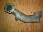
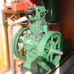
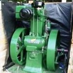
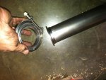
Turbo: yesterday I drove by spd in rancho cordova and picked up some mandrel bent 2.5" exhaust tubing to begin fabbing the first few feet of exhaust pipe downstream of the turbo. I need to graft the new tubing onto the old section that is configured for the packing that fits into the trw turbo's exhaust outlet. That piece was salvaged from a corvair spyder. I'm including a pic of an original 152t installation. The corvair piece doesn't stick out near as much as the IH piece before going into its bend, but it will work. My dry fit-up confirms the need to make the first 18" horizontal because of clearance issues with one of the exhaust retainer's nuts and also due to the oil fill location on the valve cover that didn't exist on the original 152t engine. I also will need to weld on a bung for a wide-band o2 sensor.

In the 152t pic you'll see a primitive heat shield surrounding the exhaust housing. Those are of course unobtanium at this time, but I have fashioned an approximation of that piece from the firewall shield of a 90s volvo turbo-diesel. Similar material and formable.
IMG_0750.jpg

IMG_0752.jpg

IMG_0753.jpg

152T late (Small).JPG

IM002222.jpg

IM002221.jpg
 
Last edited:
I have a stationary diesel, a lister cs clone that is used to backup our off-grid home. It has exposed push rods (chrome even) and when it's really cold they will not spin. After it's warm they both spin pretty good.
 

Attachments

  • lister1.jpg
    lister1.jpg
    26.3 KB · Views: 355
Relieved summer is over - spent a month out of state dealing with stuff that makes me wonder when I finally get a vacation….anyway, now taking some time to tinker and improve my mental health. Since I plan on using a side draft carter yh carb, it will need an air cleaner, so why not use a corvair spyder air cleaner? I had an early version on hand but wanted to upgrade it for "modern" controls, I.e., a thermostatically controlled hot-air snorkel for cold weather operation. I salvaged the snorkel from a Scout II v-8 air cleaner that was otherwise junk to graft onto the spyder air cleaner, whose snorkel is just a flattened tube. At this time I am thinking that when all is finally mounted, the snorkel will need to mount upside down, but that's no problem in terms of operation. In case you are wondering, my measurements indicate at least 20% greater surface area on that corvair turbo air cleaner element than on the element used for the Scout v-8s, so air flow should be more than adequate. Here are pics of the donor air cleaners before and "after" surgery.
IMG_0856.jpg

IMG_0859.jpg

IMG_0862.jpg

IMG_0867.jpg
 
Last edited:
And finally these. I will tack weld the snorkel to the canister, and fill any gaps with seam sealer, then a coat of black wrinkle-finish paint. The little thermostat that operates the snorkel's vacuum motor will mount inside after I drill two little holes in the backside of the canister. It will look and operate like an oem part.
IMG_0909.jpg

IMG_0911.jpg

IMG_0864.jpg
 
Last edited:
Last weekend I attended the IH Sierra Fall Rallye. Someone told me that they wished I would just finish up this project. All in good natured fun, of course. I whole-heartedly agree, but unfortunately life isn't like that. Today I got to an important part - fabbing up the exhaust system. I have purchased mandrel-bent parts (two 90 degrees, two 45 degrees) two couplings, 18" of that flexible stuff, and 3' of straight. All 2 1/2" o.d. So the Scout went up on the stands and I got the head pipe dropped but haven't been able to wiggle loose the pipe from all the crimped connections, which brings me to another detail. I purchased a v-band connector kit, and am going to weld one side to the cat inlet, the other to the new portion that will snake its way up into the engine compartment and to the turbo outlet. Or vice-versa. This way, when (if) I need to put the original back on for smog, it minimizes the hassles mostly of removing welded or clamped parts. Later I'll weld a spare v-ring on the original head pipe…

after putting the Scout up on stands, I removed the heater, the 2-bolt exhaust manifold, and belts for the alternator so it can swing out of the way as it needs to clear the end of the 3-bolt manifold. Since I am keeping the cat, I also need to keep the air manifold. I cut one down to three legs (well, the '79 and '80s used 3 legs anyway) and shifted it rearward to clear the cast-iron elbow. As you can see, it all still bolts up!

After bolting up the wedge, manifold, elbow, and turbo turbine housing, I begin the fitment of bits and pieces. I cut down the corvair outlet elbow which has a special end for the packing-style gasket to accept a 90 degree mandrel bend, and then added a 45 degree bend. All is now tacked and ready to weld. I will add another 45 degree portion to what you see, which will clear the starter solenoid - barely - and the go between the frame and that bulge in the corner of the block by the bell housing. More clearance around it than I thought it would have. A rough fit-up shows me that I need another 45 bend and the judicious use of some of that flex tubing to make it all work and not look too crappy.

First pic is a shot of the stock 196 engine compartment - quite busy. Second pic is with the wedge added, and third shows the elbow to mount the turbo. I apologize for how dirty my engine looks. I have the ubiquitous leaks that are so difficult to eliminate, even on a relative fresh engine.

IMG_0922.jpg

IMG_0923.jpg

IMG_0924.jpg
 
Last edited:
Here is the elbow with the turbine housing, then with the corvair turbo stub, and then after cutting in a new piece. I'm hoping I'll have clearance for a sanden compressor, as I do need my a/c.
IMG_0925.jpg

IMG_0926.jpg

IMG_0928.jpg
 
Last edited:
I read that you are leaving the cat in the system. The biggest most important number the determine turbo efficiency is perssure dif across the turbine. The cat can kill that. Anything you can do that reduces down stream back pressure adds to the energy remaining to drive the turbine.
Also the turbo will reduce egts below the turbine. That could allow fouling of the cat.
 
Robert,
I hadn't considered the egt downstream...so the turbine could remove enough heat so the cat won't light off. That's reason enough to remove it. I fortunately made more progress yesterday in welding additional downstream tubing but haven't gotten as far as the cat. At this stage, having removed the entire system, which was actually quite simple, it will be easy to weld the v-ring to the inlet to the muffler and have a straight pipe back to that. And it would be easy to weld a matching ring to the cat's outlet and thus have a modular approach to when I need to switch it back. This could all be done in a day. What makes removing/replacing exhaust parts such a b*tch is having either welded joints or clamped joints to remove. Yesterday I needed a sawzall to remove parts, but won't in the future. As it stands now, the turbine's outlet pipe goes neatly down to that space formed between the frame rail, the body, and the corner of the block just behind the starter, just like it was designed for it. There it ends and I will fashion a piece that will slip over this end (clamp), then under the bell housing before turning a 90 and heading straight back to the muffler.

About the back pressure. I am leaving the stock 2 1/4" muffler and tail pipe in place and I really don't believe that will prove unusually restrictive, especially since the carb has a 1 1/2" throat. Since I don't have a wastegate, this should suffice to keep boost under control for the time being. I've envisioned duplicating the ancient cast iron elbow in steel and tapping it for a wastegate flange. With wastegate control, there would be other carb possibilities.
 
Love those v-rings (commonly known as band clamps). Have a 258 with a header that goes into a y before the muffler. Had a band clamp installed in front of the muffler. Allows you to drop out the section of pipe between the muffler and header flanges in minutes, making it easier to work on transmissions, clutch linkage, pull engines, etc.
 
By any name they are wonderful items. I'm tempted to add one to that joint where the "down pipe" meets the "crossing under the bell housing" pipe. :icon_mrgreen: my welding skills improved a lot yesterday. One of the "joints" ground down and looks almost like an oem weld. The next one is sound, but not so pretty. :icon_eek: I do need to add a wide-band sensor bung to where that new portion outside the turbine housing just begins.

Hondo's comment about easing accessibility makes it well worth the effort and expense.

Edit: a goofy historical tidbit is that the "marman clamp" was invented by herbert marx in the 30s. Herbert marx is better known by his stage name, zeppo marx. He was one of the marx brothers!
 
Last edited:
Took a few minutes to confirm something that really needed confirmation before proceeding: will the heater box and fan motor clear the manifolding????

The answer is a resounding yes! With room to spare. I was particularly sweating that fan motor poking sideways near the valve cover. No worries. After removing the air injection tubes, I put that super rare heat shield in place. Refer back to earlier pics in this thread as to what that looks like. It folds under the manifold to protect the starter, and forms a sort of box. I should move the washer bottle forward to where the jack (which I don't have) would mount, to protect it from its present proximity to the exhaust pipe. I plan on wrapping the pipe in a high-temp fibrous wrap I got from mcmaster-carr and used on my corvair's piping to block excess heat in the engine compartment, and also wrapping the fuel line and vent line that runs on the inside of the inner fender. I also need to solder ells on the heater core's piping to point upward and reroute the heater hoses. This all should look very tidy when I'm done.IMG_0930.jpg

IMG_0932.jpg

IMG_0936.jpg
 
Last edited:
Back
Top