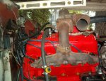
Limited disassembly of a 1980 IC 196

Just an update: I am at a point where I can consider putting on the turbo parts, but I am also at an important crossroads. I have followed with great interest an individual (dave binnie) who has successfully converted his corvair corsa from draw-through to blow-through. He originally used the single 1-bbls and now moved up to the 4 carb version. His conversion is absolutely top rate and worth googling. The pro's of going this route are now compelling. I think I can simply rotate the compressor housing to dump upward and then craft a simple u-shaped tube to go up, over, and down onto the stock Holley 1940 1-bbl throat. Sealing the throttle shaft should be easy using "air seals" as this individual has done (as shown in mcginnis' book on turbocharging). My carb presently has brass floats but they make replacements in nitrophyl, so they shouldn't collapse. I can get a rising-rate regulator as used on the maserati bi-turbo, so that takes care of that problem. The electric efi pump used on Ford trucks will supply fuel - same type pump used by bill for the efi conversions. So that is no problem. Except for blocking off the carb bowl vent, I have all the necessary check-valves so that I can retain all of my emissions devices and power brake booster. Here is the only area that will require some development. In his original conversion, dave used the stock corvair rochesters that had no enrichment circuit ("power valve") because the carbs with the pv channels were huge and flowed way too much fuel. So he opted for larger mains to cover this. His later version with the 4 one-barrels uses the secondaries for this purpose. Okay so far. My problem with the Holley is that once boost begins, I will run progressive leaner and I don't want to simply mask things with an overly large main jet. What to do: it appears feasible (maybe) to drill out the pv restrictor and make it flow right, but it would then be too Rich for normal enrichment, but that May not be a terrible situation. The other notions I'm investigating are adding a single small fuel injector to trigger when I hit, say, 2-3 lbs. Boost. Or this: I'm asking bill usn-1 his thoughts on configuring a efi computer to simply trigger a small injector in a linear fashion in response to boost pressure. Efi parts are so common these days.... In any event, dave binnie tells me he runs a wide-band sensor and is running around 12.8:1 a/f which is towards the leaner side of lambda. With datalogging I could fine tune the boost enrichment phase.
 
One issue would be is that on a blow through design a Holley pv won't work because they work off vacuum. Perhaps that's why the rochester's?

While I'm not a big fan of FI in na applications, for your turbo app it might be the best way to go.
 
That's what I said. Pv enrichment all in when manifold pressure is near ambient. Then one needs to begin enrichment to account for boost. The rochesters were interesting. The early corvair versions had no pv or equivalent. Later versions had a simple passage with a small weight that blocked the passage under vacuum and when it dropped, so did the weight and flow began. Sort of hinkey, but it worked. Binnie says those passages could be over 0.020", which is huge, making things waaaay too Rich.

I sent bill a pm on this, and am awaiting his response. Another option is to use a nos fogger nozzle and hook up the output from the efi pump to a nos solenoid. On/off, but better than nothing. An efi computer tailored to progressive flow is ideal, but will require a bit of development. Except for the megajolt ignition, retaining all the smog junk - and great tail pipe numbers - just might Make my vehicle amenable to the referee station granting an exemption, if I ever got to that point. And was still in CA.
 
Actually the pv worked off of delta-p. P1 is the air horn (fuel bowl) p2 is the manifold pressure. The differential between the two p's motivates the pv to open/close. The spring being the calibrating factor and constant.

On the draw thru application you'll need to boost reference the pv with the pressure signal from after the turbo. So anytime the engine is seeing above x map you enrichen the afr. How much is up to the pv metering orifice.
The 1904 pv needs to see the airhorn inlet so plumb the bowl vent to the air filter housing and push a beebee in to the existing 1904 pv signal port and port the cover to the manifold pressure.
 
Last edited:
Kinda. The stock pv sigs can still be under vacuum from the turbo drawing on the carb, while the engine map is at 2 psi or whatever above ambient pressure.
The reason to boost reference the pv. :icon_rotate:
 
Just so I understand what Robert is saying, the vacuum rating of a pv is relative to the difference across the venturi and not absolute to the atmosphere. Correct? Similar to psig vs. Psia.
 
More on pv function imo. :icon_xd:
it serves two purposes.
1) supplement the metering system with fuel when venturie velocities are low and fuel sigs are weak so it keeps the transition smooth with no dead or lean spot.

2) enrich the arf to say 12-1 at wot and high power conditions so peak power is given.
 
just so I understand what Robert is saying, the vacuum rating of a pv is relative to the difference across the venturi and not absolute to the atmosphere. Correct? Similar to psig vs. Psia.

Yes, only because the pv motive diaphragm sees the p1 and p.
On holly's (2300 for reference) the pv sees bowl pressure which is plumbed to atmospheric + air horn, and manifold pressure to the other. Both can be variable to some extent.

If you only consider sea level standard pressures 14.7 psi, the spring and the manifold pressure side, it functions on absolute.
At altitude and under some boost applications the calibration sees the other variable. Then the calibration is more differential.
 
To be clear, I think we are talking of two different conditions (I think). Regarding a draw-through, I get that. You can have a strong vacuum in the carb, and the pv circuit not activated, while making boost on the other side. Lean = boom! So the signal to the pv is moved to the downstream side of the compressor. Explained in mcginnis' book. The thing, then, is you have the right signal, but then need to richen accordingly. Now, I am talking about a blow-through. Here you go wot, but no boost - yet. Little or no vacuum, pv is activated. Now as the engine continues towards boost, the pv is contributing all it can already, and then you encounter lean unless you can richen things up past that point. Which means a pv that provides a certain level of additional richness up to 0 vacuum, but would somehow need to increase this when going to positive pressures.

Regarding the 1904 used on the 152t. It appears that they just used a bigger main jet and used the stock pv. The main covered the sins of leaness under boost. Probably terribly Rich when not under boost, or most likely, terrible all the time! But not leaning out and detonating into oblivion.

I am seriously considering blow-through using the stock Holley 1940 (not a 1904). It has a similar pintle that opens when vacuum drops, and fuel entering the pintle well flows to a small restrictor, a jet, really, that provides whatever richness the pv is supposed to provide. But while the pv won't provide added richness commensurate with positive pressures, you also won't have the draw-through situation of having a vacuum signal on one side and boost on the other. Just a lean-ness that grows in a linear fashion as manifold pressures go from negative to positive. Still a problem that needs a solution. :crazy:
 
In blow through application and an odd bird like the 1940, it will need to go in a box that encapsulated the entire carb in compressed air.
Bad thing on that is that the variable air density can not be fully dealt with by the venturies. Once on boost up stream of the carb, limited by the waste gate it'll be ok assuming you calibrated it there.
Off boost it'll be like driving a carbureted engine in mammoth, pig Rich. :idea:

I have weighed the choices and feel either go with a non pv carb on blow thru or draw thru on whatever, which is what I plan on doing.
 
Maybe I should revert back to the original plan. A draw-through using the side draft yh. At least I know it will work at least as well on the corvair, and there are choices in metering rods. So getting to an acceptable (read: not ideal) a/f under boost is doable.

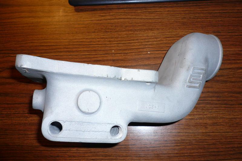
So back to casting a carb-to-compressor adaptor from aluminum.
 
Wheew, this was beach to cast:d
if I only had a box full of'm..........

My planed carb plenum. Also water heated to stop the dreaded icing and subsequent turbo choking in ice cubes. :frown2:

19206d1361206913-ultimate-IH-fourbanger-p1010702-medium-.jpg


19207d1361206913-ultimate-IH-fourbanger-p1010705-medium-.jpg
 
Some in the corvair crowd run an adaptor like that. Uses oil for heat because a corvair doesn't use a lot of antifreeze in its cooling system. :roll eyes: recirculating some of the exhaust hot air also helps. At times I could see frost develop on my cross-over pipe. If I find it too troublesome (translation: beyond my skill level) to cast in a cavity for heating liquid, then I'll just take advantage of the heated air ducted to the snorkel. That will prevent icing. If you look at the original carb stand for the 152t, you'll see it held a lot of hot water. Ran in series with the heater hose outlet from the intake manifold, to the stand, to the heater core, into the water pump. Great on a snowy day, but a killer in the Arizona heat. Today one could simply plumb in a bypass using a vacuum operated heater valve ('80s GM) signaled from a tvs. Think how the egr is switched off below around 130 degrees. Do the same thing with a heated adaptor. Gee, looks like I've already given this contingency a lot of thought. :winky:
 
Last edited:
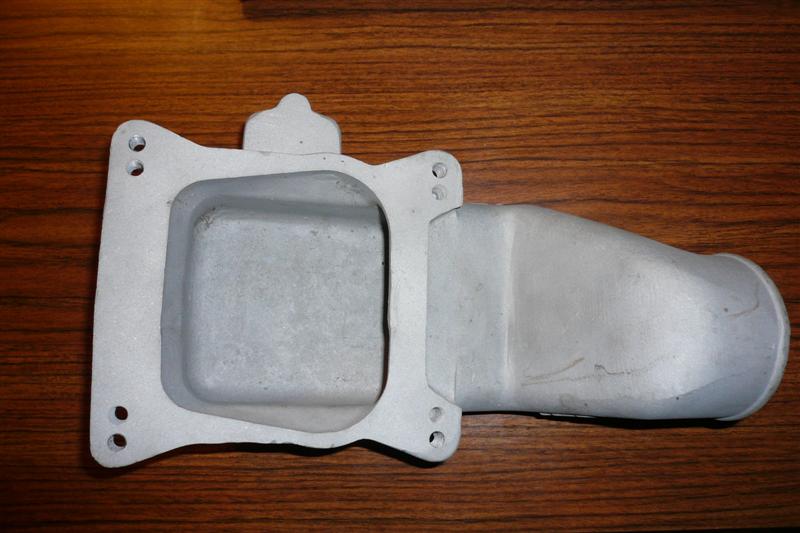
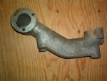
This. I had originally thought this adaptor would be a useable piece, at least in theory, but not necessarily ideal. Imagine rotating this image a little bit clockwise to where the carb mounting pad on the right, is horizontal and parallel with the top and bottom of the image frame. The coolant goes into the higher boss on the left, exits beneath the carb through the boss on the right. There is a large cavity running along the underside of the intake runner. The ic 196 head is taller and therefore this part would have to rotate even further ccw than it is here relative to the picture frame, to clear the intake. If this adaptor had been useable, a suitable downdraft carb for a draw-through would be an autolite 1100, which is roughly the successor to the carter downdraft from which the yh sidedraft was configured. The autolite was used on a Ford 200 c.I. In-line six. This carb has a metering rod/jet, which lends itself to proper tuning. It just dawned on me that if I were to saw off the water chamber, perhaps the intake runner portion beneath would clear the intake manifold. Hmmm.... I have two of these ultra rare adaptors but can't imagine the modification of one would be a loss to the automotive world. The diameter of the runner at the top matches the intake of my modified compressor housing, and boring out the hole where the carb sits a quarter inch to accomodate a larger 1-bbl is feasible (it's 1 1/2" for the original Holley 1904 vs. 1 11/16" for a larger 1904 or 1940)....
 

Attachments

  • Intake adaptor (Small).jpg
    Intake adaptor (Small).jpg
    45.8 KB · Views: 455
Last edited:
An update before I leave for vacation….

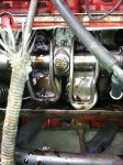
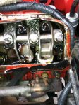
About that pushrod that didn't rotate: that really bugged me, and today I confirmed what I suspected was the cause for that, or at least seems to be the most reasonable explanation at this time. The answer was in plain sight. When I first fired up the engine, what did I have? A relatively cold engine with relatively cold oil, even after running it for 30 minutes. Then later on in checking it out, the engine had never truly been run up to warm/hot. Then when I hit the panic button, I had just changed out the break-in oil (heavy in zddp) to swepco 15/40, and the engine, again, was up to temp but not truly hot as the weather was mild. So today I drove it down to sacramento - first long road trip in that Scout - freeway speeds around 60 mph and it got up to temp as it's pretty warm outside. Put on the cut-out valve cover and what do you know - that pushrod now turns while idling. Not real fast but faster than before. I suspect that the oil was thick and dragging the lifter's inner body, still is, probably, to some degree, but the oil needed to warm up and thin out. My theory, anyway. However, I'm including a couple shots here of the engine turning around 1,000 rpm. The exhaust "boats" don't seem to fill up a lot, but the intakes do. Anyone noticed this before? I think it is oiling well enough, but I was surprised to notice the valve side of the boats not awash in oil.

Mileage: wow. I filled it up as much as I could before I took off down the hill, to sac, and back. Then filled up again. 70 miles on 3 gallons. No matter how I cut it, it's over 20 mpg. This at steady highway speeds at 1,000 foot elevation down to sea level, and back. I know it isn't the best test but still….

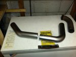
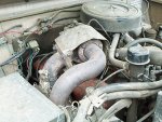
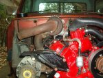
Turbo: yesterday I drove by spd in rancho cordova and picked up some mandrel bent 2.5" exhaust tubing to begin fabbing the first few feet of exhaust pipe downstream of the turbo. I need to graft the new tubing onto the old section that is configured for the packing that fits into the trw turbo's exhaust outlet. That piece was salvaged from a corvair spyder. I'm including a pic of an original 152t installation. The corvair piece doesn't stick out near as much as the IH piece before going into its bend, but it will work. My dry fit-up confirms the need to make the first 18" horizontal because of clearance issues with one of the exhaust retainer's nuts and also due to the oil fill location on the valve cover that didn't exist on the original 152t engine. I also will need to weld on a bung for a wide-band o2 sensor.

In the 152t pic you'll see a primitive heat shield surrounding the exhaust housing. Those are of course unobtanium at this time, but I have fashioned an approximation of that piece from the firewall shield of a 90s volvo turbo-diesel. Similar material and formable.
IMG_0750.jpg

IMG_0752.jpg

IMG_0753.jpg

152T late (Small).JPG

IM002222.jpg

IM002221.jpg
 
Last edited:
I have a stationary diesel, a lister cs clone that is used to backup our off-grid home. It has exposed push rods (chrome even) and when it's really cold they will not spin. After it's warm they both spin pretty good.
 

Attachments

  • lister1.jpg
    lister1.jpg
    26.3 KB · Views: 411
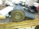
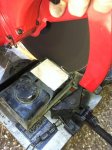
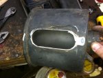
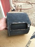
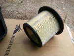
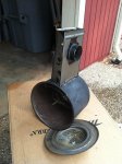
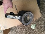
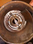
Relieved summer is over - spent a month out of state dealing with stuff that makes me wonder when I finally get a vacation….anyway, now taking some time to tinker and improve my mental health. Since I plan on using a side draft carter yh carb, it will need an air cleaner, so why not use a corvair spyder air cleaner? I had an early version on hand but wanted to upgrade it for "modern" controls, I.e., a thermostatically controlled hot-air snorkel for cold weather operation. I salvaged the snorkel from a Scout II v-8 air cleaner that was otherwise junk to graft onto the spyder air cleaner, whose snorkel is just a flattened tube. At this time I am thinking that when all is finally mounted, the snorkel will need to mount upside down, but that's no problem in terms of operation. In case you are wondering, my measurements indicate at least 20% greater surface area on that corvair turbo air cleaner element than on the element used for the Scout v-8s, so air flow should be more than adequate. Here are pics of the donor air cleaners before and "after" surgery.
IMG_0856.jpg

IMG_0859.jpg

IMG_0862.jpg

IMG_0867.jpg
 
Last edited:
And finally these. I will tack weld the snorkel to the canister, and fill any gaps with seam sealer, then a coat of black wrinkle-finish paint. The little thermostat that operates the snorkel's vacuum motor will mount inside after I drill two little holes in the backside of the canister. It will look and operate like an oem part.
IMG_0909.jpg

IMG_0911.jpg

IMG_0864.jpg
 
Last edited:
Back
Top