

You are using an out of date browser. It may not display this or other websites correctly.
You should upgrade or use an alternative browser.
You should upgrade or use an alternative browser.
152 rebuild
- Thread starter Mastiff
- Start date
Mastiff
Member
My engine is back home now, ready to be built. I just painted the block. Any thoughts on painting the head? There's hardly any surface to be painted and masking everything off would be quite a chore. What do you guys do? One obvious option is to wait until it's together, then paint everything, although my exhaust manifold is not painted red.
By the way, anyone know if oil pump gaskets are attainable? We noticed that it was catching a little as it was turned and opened it up to find tiny specks of metal in there, almost certainly from the crank. The gears look good though, so I just want to thoroughly clean it up and put it back together. The gasket self destructed on disassembly though.
Thanks.
Robert Kenney
Super Moderator
If you buy gasket material like heavy paper you can cut one out.
The material I am thinking of is about .025-.030 thick and grey. Don't use cork.
But you May be refering to the oil pump cover and in that case idk without buying the pump rebuild kit.
Fyi that pump is availible new.
The material I am thinking of is about .025-.030 thick and grey. Don't use cork.
But you May be refering to the oil pump cover and in that case idk without buying the pump rebuild kit.
Fyi that pump is availible new.
Ooh, that little scene in the rebuild movie begs cut! Cut!we noticed that it was catching a little as it was turned and opened it up to find tiny specks of metal in there, almost certainly from the crank.
Have you sterilized everything? I mean, wash, douche, and again with brushes and bore brushes getting every hole and gallery clean throughout?
Mastiff
Member
if you buy gasket material like heavy paper you can cut one out.
The material I am thinking of is about .025-.030 thick and grey. Don't use cork.
But you May be refering to the oil pump cover and in that case idk without buying the pump rebuild kit.
Fyi that pump is availible new.
Yeah, the one between the two "halves" of the oil pump. It looks like a very thin sheet of black plastic or wax paper right now. I don't know what it looks like new.
The rebuild kits are $80 and new pumps are $120 or so. At those prices, doing a rebuild is hardly worth it to me. Not that there's much to it, must be new gears and a gasket...
Mastiff
Member
ooh, that little scene in the rebuild movie begs cut! Cut!
Have you sterilized everything? I mean, wash, douche, and again with brushes and bore brushes getting every hole and gallery clean throughout?
The machine shop did everything under the sun. The bill was 2 grand. A little more than I expected going in, but I could tell it was going to add up as we worked through it. I have new pistons, a "new" crank, rebuilt head, bored and decked block, everything cleaned. No worries there as long as I don't contaminate it myself during rebuild.
Turns out they couldn't save the crank. They went down 0.03 and it still wouldn't clean up. We found a good one locally. Is the old one worth anything, or should I make it into a lamp or something...
Eric VanBuren
Member
New pumps are available from a number of resources and they are not that expensive compared to the cost of a rebuild, so I wouldn't put anything other than a 100% new pump in there. The melling number is m71. Depending on where you shop it can be had for about the price you've been quoted for a rebuild kit.
I'm sure for $2k they did a lot. With that kind of investment for "my" engine, I would leave nothing personally unchecked unless is was a "built by kenney" engine
many years ago, (gull damn to think about it it was long), I did a 289 for a guy. It too was hot tanked, and that was with the good stuff. It was beautiful to behold, but I found a gallery that still had some crud. Maybe not enough to screw up anything, but still it was a good thing to find and clean out. The crank too was machined, and still all holes were cleaned out and the oil passages needed chamfered.
The oil pump specifications show the thrust clearance is .0015" to .006", you gasket between the pump body and cover to that specification; one or a couple of thin gaskets are used to attain that. You could make your own as Robert suggested.
Then again, just looking good don't mean much as it really needs measured to determine suitability.
Push your thumb down on the gears, the gear to body clearance is .0014" to .005" measured with a feeler gage.
Holding the driven gear, measure the idler gear backlash, it should be .003 to .006"
shaft clearance is .001 to .002", it's work to take apart and measure so let's say any wobble however slight is cause to toss it.
If you take the cotter pin out of the relief body, you can check the relief valve spring and valve. Unloaded, the spring must measure 3 to 3 11/32". The bore must be clean, no varnish, and the valve to bore clearance is .004 to .008.
With all that, you can see why a new pump can be good insurance.
Last edited:
Robert Kenney
Super Moderator
It doesn't matter who does the machining, if you have a pile of parts and you will be the one putting it back together, you are responsible for checking everything.
leave no stone unturned. Check everything, main saddle bores, assembled main bearing id's, rod big end bore and assembled bearing id. Measure every crank journal od's in no fewer than 4 places. Calculate all bearing clearances. They should be dead nominal if the machine work is good.
Measure each piston and each bore for running clearance. I can't tell you how many piston sets I have recieved that had one slug way under. The last one was exactly .005 under to the tenth of a thousand. I assume the guy running the machining line missread the micrometer. That would have destroyed the build and I would have had to eat the repair cost.
The main bearing clearances are critical to proper connecting rod oiling and valve train oil supply. Also important for lifter gallery pressure. I would recommend nothing bigger than .003 with .002-.0025 preferred.
Last edited:
Mastiff
Member
I've got a friend helping me out with this who has done a bunch of engines. I don't think he's at you guys' level, but he worked in a machine shop a while and has built a number of engines that run well. I'm going to let him be lead, I'm not sure if he'll be as thorough as you guys are talking about. I'm over my head a little.
The guys at the shop told me that they gave it to me in the same ready condition as though they were going to do it themselves. If I paid them $400 more, they would have started bolting things together. That eases my mind some.
I was looking at the rear seal setup with the two rubber "dowels" and all that. Do you guys have any pointers (a) on how to get those things in, and (b) how to generally prevent rear main leaks down the line? I know I need to install the rubber dowels and punch in the seal, but should I do anything like coat the dowels with rtv, put rtv in the cracks around the rear cap, etc?
Oh, and do you suggest rtv for the rear cam cap gasket?
Thanks.
Robert Kenney
Super Moderator
I was looking at the rear seal setup with the two rubber "dowels" and all that. Do you guys have any pointers (a) on how to get those things in, and (b) how to generally prevent rear main leaks down the line?
I know I need to install the rubber dowels and punch in the seal, but should I do anything like coat the dowels with rtv, put rtv in the cracks around the rear cap, etc?
The rear main cap parting line is a possible source of leakage, so a very thin coat on a non hardening sealer ( aviation ptex) just before assembly. See picture.the red box is the location on both sides.
A light coating of ultra black in the hole and on the plug. Then push them in using a 1/8 diameter pin on some sort. I have used long nails after grinding the tip to a smooth half round. The small flange will need to rest on or just above the top of the rear main cap.
Oh, and do you suggest rtv for the rear cam cap gasket?
Thanks.
I like "moto seal", "theebond 1194" or fka"yamaha bond 4" for all of the permanent gasket interfaces that can't dare be allowed to leak. It is thin and light grey. It was developed for the assembly of motorcycle engine case half's and other metal to metal gasket less assemblies. It works great in areas like the rear cam cover. Performance aircraft builders have been known to use it instead on the silk thread and tite seal sealant commonly used at the cylinder case half parting line.

Mastiff
Member
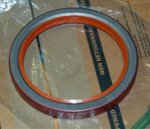
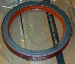
I want to make sure I get the rear main in correctly. Can you guys tell from these pics which way is out? I'm thinking pic #1 is the out facing side. Does that look right? I'm mostly going by the seam in the metal on the other side.
Notice the dent? I almost didn't spot it.


Notice the dent? I almost didn't spot it.
Attachments
Robert Kenney
Super Moderator
In your first picture, the visible side goes out.
Needs to be pressed in after the rear main cap is torqued. Don't install and then tighten the main cap. I mention this because the paint and pinched metal shavings will end up between the cap anc block causing screw up main bearing clearances. Seen it happen.
Another hint. Just barely get is started being pressed in and using a smooth pin or pick run the pick between the crank and seal lip so you car be sure it doesn't get bound and damaged while driving it in. Easier to show than explain. Sorry
Last edited:
Mastiff
Member
in your first picture, the visible side goes out.
Needs to be pressed in after the rear main cap is torqued. Don't install and then tighten the main cap. I mention this because the paint and pinched metal shavings will end up between the cap anc block causing screw up main bearing clearances. Seen it happen.
Another hint. Just barely get is started being pressed in and using a smooth pin or pick run the pick between the crank and seal lip so you car be sure it doesn't get bound and damaged while driving it in. Easier to show than explain. Sorry
I think I know what you're getting at. While we're on the subject, how do you go about getting that seal in technique wise? The manual calls out a special tool which I assume nobody has anymore. Is it going to be possible to carefully pound it in, or do I need to rig up something? I was able to carefully pound the front main in, though I was sure nervous about the aluminum cracking on me.
The rear is made harder because the engine is in the stand. I could wait until it's on the hoist, but then everything is swinging around.
Thanks.
Mastiff
Member
Robert, did you post something and then delete it? I got an e-mail notification but I don't see anything new here. I think you said to wait until the engine is out of the stand to do the rear main. I've been trying to follow the manual, but they seem to have everything in strange order. Cam first, then crank, then front and back covers, flywheel, clutch ... Then pistons. We're putting the pistons in after the crank. It seems like all that back end stuff can wait until the engine is about to be installed.
Robert Kenney
Super Moderator
Only way I know is with a seal driver I made. Like the oem tool
the rms and rear freeze-plug both go in after removing from the stand.
Software glitch.
the rms and rear freeze-plug both go in after removing from the stand.
Software glitch.
Robert Kenney
Super Moderator
Again I made an alignment tool but, press the seal in and do as you described. Align the cover using the hub. You just want to center the seal lip preload on the hub.
Robert Kenney
Super Moderator
Mastiff
Member
pic of alignment tool. Made on lathe and mill.
Nice!