152 rebuild

Got it out. That's kind of an adrenaline rush for someone like me who doesn't really know what's going on. I ended up removing the mounting bracket from the engine on one side to get it free. The other problem I had was that the flywheel inspection cover was interfering. I didn't think it would need to be removed, but I should have guessed since it was heavily damaged. I now know that the last guy to pull the engine had the same issue. I May be looking for a replacement cover since I'm down to two usable mounting holes.
 

Attachments

  • hoisted3.jpg
    hoisted3.jpg
    59.6 KB · Views: 808
Here are some more pics for the record.
 

Attachments

  • hoisted1.jpg
    hoisted1.jpg
    48.4 KB · Views: 367
  • hoisted2.jpg
    hoisted2.jpg
    48.9 KB · Views: 354
  • hoisted4.jpg
    hoisted4.jpg
    46.1 KB · Views: 350
  • stand1.jpg
    stand1.jpg
    54.2 KB · Views: 367
  • stand2.jpg
    stand2.jpg
    50.5 KB · Views: 367
  • stand3.jpg
    stand3.jpg
    76.3 KB · Views: 349
So, what should I do next? Should I just start dismantling stuff? Should I get a rebuild kit on order now, or wait until I know the condition of some of the internals?
 

Attachments

  • stand4.jpg
    stand4.jpg
    49.8 KB · Views: 804
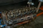
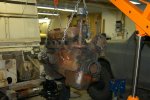
Pull it down all the way.

As ya go, you will develop a parts list.

Do not order in any parts until ya know exactly what condition the cylinders, cam, cam bearings, head, crank, etc. Are in. And that comes only through proper measurement of all the critical points.

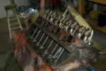
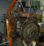
I dropped a 196 at the machine shop today in pieces. Three cylinders were out of tolerance by just a hair, #4 was worn dam near first oversize. This block had already had bucks spent on it for bake and blast, even though the crank was totally unusable as is!

The rods had also been cleaned but then thrown in a box after the worn out pistons were removed so they are all mixed up...the small ends have significant rust now on the machined surfaces, the rods are gonna have to be checked for end size and straightness and May have to be rebuilt before the new pistons are installed.

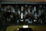
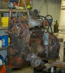
And the "other" 196 in the shop now (the one that started this whole mess) is in the same condition, the crank is beyond usable without being ground.

The "best" camshaft that is suitable for a core for regrind has two lobes down by 0.020". So it must have some luv also. A full engine kit was obtained in advance for the motor by the owner, but due to the condition of both engines, the only parts usable now are the gasket set, cam bearings, and soft plug kit. The rings, mains, rods, are gonna have to sit on the shelf and hopefully at some point I will have an I-4 motor that needs a simple freshening.

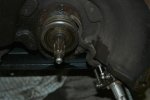
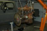
And because a different flywheel is being prepped for this motor, along with a bore job and oversize pistons, the rotating assembly (even the flywheel bolts) is being balanced.

So to sum up...I've got two 152 motors in pieces, along with two 196 motors down. None of the crankshafts are usable as is, only one of the 152 has usable bores as far as not having to be bored, and three of the four cams are crap along with all four blocks have grunched cam bearings.
 
Ditto what mayben said, as it is my 196's that are hogging space up at binder u..... Lesson learned verify and check before you order. Don't assume that everything is going to be okay.:idea: also, it's going to cost more than you think.:ciappa:
 
Started tearing everything apart tonight. No real issues so far. I did have some questions for you guys though. First, looking at the transmission side of the bellhousing (is that the right term), it looks like the holes on the bottom on each side are bigger than the others. The manuals speaks of sleeves or something like that, and I think I can see something in their picture. Are there supposed to be sleeves in those bottom holes? If so, I don't have any. I'm certain they didn't fall out when I pulled it apart.

Next, what should I look for to decide if my throwout bearing is good to go? It has slop in it (side to side) but I'm not sure if that's normal. Also, some indentations where the fork presses. Not sure if that's okay either. That whole slave cylinder setup is kind of a sloppy operation with the angles and range...

Thanks for the help.

Oh, one other question. Is it necessary to keep track of how the clutch and flywheel are oriented, for balance reasons? I already removed the clutch, so hopefully the answer is no.
 
Last edited:
started tearing everything apart tonight. No real issues so far. I did have some questions for you guys though. First, looking at the transmission side of the bellhousing (is that the right term), it looks like the holes on the bottom on each side are bigger than the others. The manuals speaks of sleeves or something like that, and I think I can see something in their picture. Are there supposed to be sleeves in those bottom holes? If so, I don't have any. I'm certain they didn't fall out when I pulled it apart.

Next, what should I look for to decide if my throwout bearing is good to go? It has slop in it (side to side) but I'm not sure if that's normal. Also, some indentations where the fork presses. Not sure if that's okay either. That whole slave cylinder setup is kind of a sloppy operation with the angles and range...

Thanks for the help.

Oh, one other question. Is it necessary to keep track of how the clutch and flywheel are oriented, for balance reasons? I already removed the clutch, so hopefully the answer is no.

The flywheel will go back on the crank only one way due to the dowel location. Not necessary to keep the clutch cover in the original position, but it's always standard practice to do so if you are going to re-use.

The clutch throwout fork and throwout bearing sleeve should be reworked or swapped for a reconditioned set:

http://www.forums.IHPartsAmerica.com/new-products-IH-only/1862-Scout-80-clutch-components.html

Additional reconditioned clutch fork sets are on their way to ihon in Loomis.

Always replace the throwout bearing and pilot bearing when an engine or tranny is out...standard practice if the age/operational hours of those parts are unknown!

The two lower holes ya mention in the lower/rear of the engine bell should contain alignment dowels...very important! Those align the centerline of the transmission input shaft with the centerline of the crankshaft. The dowels May be in the clutch bell or in the engine, or one of each. Doesn't matter which part they stay with as long as they are present. You will also find a similar dowel in the block's deck at each end for cylinder head alignment. And new replacement dowels are in stock now at ihon.
 
Ripped most of the rest of the easy stuff off tonight. Check out the picture of the intake manifold. The one coolant opening is solidly plugged with something resembling concrete. This can't be right, right? There's an opening on the head there, so I'm kind of confused why someone would do this.
 

Attachments

  • intake.jpg
    intake.jpg
    59.6 KB · Views: 802
Here are some misc pictures for the record. I pulled the plugs out and was turning the engine over and over trying to understand the timing of the valves. I put the distributor back in the way I thought it was originally, but heck if I can get it to come around to where the #1 plug wire is when I think it should according to the valves.

Hypothetically speaking :rolleyes5:, how would a person go about installing the distributor properly if he just showed up cold and had to figure it out with no information?
 

Attachments

  • rockers.jpg
    rockers.jpg
    59.1 KB · Views: 347
  • rods.jpg
    rods.jpg
    60.4 KB · Views: 355
  • crank_in.jpg
    crank_in.jpg
    52.4 KB · Views: 329
Here's a shot of the throwout bearing and fork. A friend came by tonight and he's certain it's shot based on the amount of slop in it. Is the bearing a press fit onto the collar?

I'm leaking a lot of oil from the front of the trans. I can access the seal from here, right? Is there a front bearing I can access from the front also?
 

Attachments

  • throwout.jpg
    throwout.jpg
    39.6 KB · Views: 758
here are some misc pictures for the record. I pulled the plugs out and was turning the engine over and over trying to understand the timing of the valves. I put the distributor back in the way I thought it was originally, but heck if I can get it to come around to where the #1 plug wire is when I think it should according to the valves.

Hypothetically speaking :rolleyes5:, how would a person go about installing the distributor properly if he just showed up cold and had to figure it out with no information?


There's a thread here somewhere describing the "stabbing" procedure for distributors in these vehicles. To find the #1's tdc, put a soft rod or dowel or whatever in the plug hole and "feel out" when it tops out. I think intake will be closing a little after bdc, so start turning more slowly after you witness that valve event.

You also have to account for the fact that the teeth in this gear are cut at an angle, which means you must "offset" your ideal timing position. It's because of this that a lot of people stab it straight-down and get it a tooth or two off as it follows the angle, enough to where adjusting the body won't make up for timing.

So don't forget to look at those teeth before you install it and remind yourself to "back up" and allow the teeth to bring it into position. You also have to make sure there is some kind of brass(?) bushing seated correctly down below to bear the gear-end of the distributor shaft, too. I highly recommend getting more information from the thread I can't seem to find.
 
Last edited:
ripped most of the rest of the easy stuff off tonight. Check out the picture of the intake manifold. The one coolant opening is solidly plugged with something resembling concrete. This can't be right, right? There's an opening on the head there, so I'm kind of confused why someone would do this.

That is the originally-engineered exhaust heat crossover passage. Since your engine is a very early model, I would have expected to see that passage "open" but have a blocker segment incorporated into the intake gasket.

Exhaust heat was not used nor needed on the 152 engine in the Scout 80, but was most likely used on that engine when used inna tractor, bailer, or as a pump engine...all common uses.

This engine was manufactured in this manner, that is not a po virus deal! Some manifolds were "plugged" with some type of epoxy material back in the day...later aluminum manifolds simply had the runner left in the mold/casting, but the actual passage was blocked during the foundry process.

This shot is a very early 152 intake that has a functional exhaust heat crossover. I installed it on the engine in the pics I posted swinging from the hoist (the refurbished motor). This is the only one I've personally had my mitts on, but I've played with many just like yours...I have three of 'em now!
 

Attachments

  • VERY EARLY 152 Intake.jpg
    VERY EARLY 152 Intake.jpg
    122.2 KB · Views: 767
here are some misc pictures for the record. I pulled the plugs out and was turning the engine over and over trying to understand the timing of the valves. I put the distributor back in the way I thought it was originally, but heck if I can get it to come around to where the #1 plug wire is when I think it should according to the valves.

Hypothetically speaking :rolleyes5:, how would a person go about installing the distributor properly if he just showed up cold and had to figure it out with no information?

Simple version for a 152/196:

1) align timing Mark on crank hub with zero tick Mark on timing quadrant, cylinder #1 must be at tdc on the compression stroke, not the exhaust stroke!!

2) with cap removed and the #1 terminal on the cap marked on the distributor body with a marker, align the tip of the rotor with the Mark on the distributor body.

3) rotate the distributor shaft/gear slight ahead of where the Mark on the body is to allow for the helix angle of the drive gear...as you face the engine, the vacuum advance can should be facing you and on the right side for proper rotational clearance.

4) stab it in, aligning the oil pump drive tang as it goes in.

You can make any of the four cable sockets on the cap to be #1 when you align the rotor. Just make that hole #1 cylinder and then go around the cap clockwise and install the plug cables in the firing order pattern: 1, 3, 4, 2.
 
here's a shot of the throwout bearing and fork. A friend came by tonight and he's certain it's shot based on the amount of slop in it. Is the bearing a press fit onto the collar?

I'm leaking a lot of oil from the front of the trans. I can access the seal from here, right? Is there a front bearing I can access from the front also?

The throwout bearing is a very "light" press fit, the collar May be driven out of the bearing with a light hammer and drift.

The collar must be "renewed" along with the throwout fork, see those two heavy wear points??? Those will be "moved" when ya install a freshened collar on a reconditioned fork so there is only a slight running clearance between the fork tips and the collar groove. That wear is why you cannot use over one-half of your slave cylinder travel to release the pressure plate! And you May also see that the clutch throwout arms have actually eaten into the fork itself. Then a replacement throwout bearing is tapped onto the collar.

You can access the seal and gasket on the front nose of the tranny, but do not pull out on the input shaft while the bearing retainer is removed!!!!!
 
The manual tells me to use a ridge reamer on the the cylinder prior to removing the pistons. Is this a necessary step? I don't have a ridge reamer of course...
 
the manual tells me to use a ridge reamer on the the cylinder prior to removing the pistons. Is this a necessary step? I don't have a ridge reamer of course...

Feel along the top of each cylinder where the top ring's travel ends - is there a definite ridge? I would think that unless this ridge is large enough to feel, it won't provide serious interference.

If you can take the pistons out, take them out - just don't forget to find a way to determine wether or not a ridge exists. A precision straightedge or small rule plus a good set of tiny feeler gauges might help here. This would be something I'd do when checking cylinders for elliptical wear and overall wear.
 
Yeah, there's a ridge. It doesn't seem huge, but it's there. The pistons won't come out easily. Should I go find a reamer, or will they come out the back way for me if I get the crank out?

Also, any advice on getting the harmonic balancer off? I borrowed a puller from the parts store, but it's not big enough to span all the way across. I'm assuming there's another kind of puller that will do it.

Here's a pic of my carbon laden pistons not coming out. Is this amount of carbon extreme, or pretty typical for an old motor like this?
 

Attachments

  • piston_carbon.jpg
    piston_carbon.jpg
    31.6 KB · Views: 716
Here's a pic of the bottom side of the head. How do the valves look to you guys? I think my plan is to take the head to a local shop and have them do the checkout/rebuild. I'll have them dip the block also.
 

Attachments

  • cylinder_head_bottom.jpg
    cylinder_head_bottom.jpg
    43.3 KB · Views: 765
I think I found my first serious casualty. Check out the crank where the #3 rod was removed. It's seriously scored. The rod was attached with different bolts than the others, though it seemed tight. Someone was messing with it. Can I recover from this, or do I need a new crank?
 

Attachments

  • damaged_crank.jpg
    damaged_crank.jpg
    50.9 KB · Views: 721
yeah, there's a ridge. It doesn't seem huge, but it's there. The pistons won't come out easily. Should I go find a reamer, or will they come out the back way for me if I get the crank out?

Also, any advice on getting the harmonic balancer off? I borrowed a puller from the parts store, but it's not big enough to span all the way across. I'm assuming there's another kind of puller that will do it.

Here's a pic of my carbon laden pistons not coming out. Is this amount of carbon extreme, or pretty typical for an old motor like this?

I would recommend finding a reamer, but I've never hands-on done any of this - I just know that you might as well do it yourself instead of paying someone, if you can get your hands on a reamer and it's easy enough to use. I can't say anything about the balancer for lack of experience.

As far as the amount of carbon - that looks extreme, but I guess any old motor I've seen that has experienced heavy use (maybe abuse..?) looks like a lesser degree of your own situation. It's to be expected, I suppose, if you're intending on investing in a rebuild.

here's a pic of the bottom side of the head. How do the valves look to you guys? I think my plan is to take the head to a local shop and have them do the checkout/rebuild. I'll have them dip the block also.

I highly recommend doing as much research as possible (asking around with locals, doing online searches, finding reviews, etc) for your decision regarding a machine shop. I would hate to hear a story of less-than-expected outcome when your stuff gets finished.
 
Back
Top