The Sonjamotor Lives!

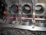
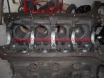
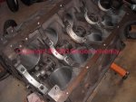
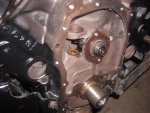
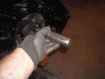
Here's the cam bearings going into the block.

We're using durabond bearings from ihon. Each bearing was verified as to proper oil hole location before setting up on the installation tool.

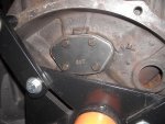
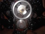
The #5 bearing (rear) is installed first, ending up with the #1 bearing (behind the cam gear). As each bearing shell was loaded on the tool, it was carefully indexed to register with the appropriate oil holes in the bearing saddle.

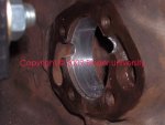
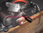
This job is much easier (and more accurate) with two folks doing it. Ya got one shot at getting the bearing installed correctly. Once the bearing is in position, then appropriate size aircraft drill bits are inserted thru the oil holes from the outside to verify proper location. If needed, the oil holes can be fudged slightly with the bits, followed by de-burring of the bearing shell.
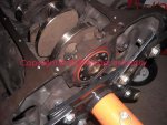
 

Attachments

  • Cam Bearing Install.jpg
    Cam Bearing Install.jpg
    95.2 KB · Views: 1,235
With the engine still on the stand, the lifter gallery feeds can be seen.

Since the cam bearing shell overhangs the oil relief slightly, we cut away a portion of the bearing (and de-burred) so that full oil flow to the lifters won't be impeded once the system is buttoned up.
 

Attachments

  • Number 5 Cam Bearing Relief.jpg
    Number 5 Cam Bearing Relief.jpg
    58 KB · Views: 1,236
Here's the upper main bearing set installed in the block. On an I-4/sv motor, the crankshaft thrust is taken through the center main.

We're using clevite 77 "bearing guard" assembly lube on this motor, applied to the shells with an acid brush.
 

Attachments

  • Main Bearing Upper.jpg
    Main Bearing Upper.jpg
    80.9 KB · Views: 1,247
The crank is torqued in place.

Yes! Assembly lube is present! And the clean main cap bolt threads were dosed with anti-seize before installing. And...as each cap is tensioned, the crank is checked for proper rotation, better to find a scruup now than after the motor is in the bay!
 

Attachments

  • Crank Installed.jpg
    Crank Installed.jpg
    98.9 KB · Views: 1,251
Before the crank was installed, the cam was stuck down the gullet and verified for proper rotation.
 

Attachments

  • Cam Install.jpg
    Cam Install.jpg
    79.5 KB · Views: 1,228
The rear crank seal supplied in this fel-pro gasket set was a 100% silicone item, not the composite seal with the teflon lip. So the lip on this seal gets a smear of assembly lube for break-in purposes.

The flange on the crank was in excellent condition with no discernible wear groove, so no repair sleeve/overlay was needed, more cash saved!

I slide the seal over the crank hub before setting the crank in place, but it's not placed in it's final position yet. Then the crank is lowered onto the main bearings, the caps are snugged into position, while making certain the seal is square in it's bore. Then the mains are torqued.

Once the short block is hanging from the hoist so that the cam plate and core plugs can be installed, the crank seal will be driven home to it's final resting place. Then the short block goes back on the stand for completion.
 

Attachments

  • Crank Seal In Place.jpg
    Crank Seal In Place.jpg
    77.9 KB · Views: 1,229
I slide the seal over the crank hub before setting the crank in place, but it's not placed in it's final position yet. Then the crank is lowered onto the main bearings, the caps are snugged into position, while making certain the seal is square in it's bore.

I want to respectfully disagree with this method of installing the main seal.

The main cap can and in many cases does shave off the paint on the metal part of the seal that ends up between the cap and the block. That paint will stop the main cap from seating properly and in the end effect the bearing clearance.

The seal should be driven in after torquing the main cap. IH lists a tool to drive it in.

On another note, did I send you back the timing set???? I can't remember.


just a note to all readers, the statements above are in no way an attack on michael mayben but an observation based on personal experience.......... :icon_rotate: :icon_rolleyes:
 
Last edited:
I want to respectfully disagree with this method of installing the main seal.

The main cap can and in many cases does shave off the paint on the metal part of the seal that ends up between the cap and the block. That paint will stop the main cap from seating properly and in the end effect the bearing clearance.

The seal should be driven in after torquing the main cap. IH lists a tool to drive it in.

On another note, did I send you back the timing set???? I can't remember.


just a note to all readers, the statements above are in no way an attack on michael mayben but an observation based on personal experience.......... :icon_rotate: :icon_rolleyes:

I hear ya Robert!

So let me 'splain....

This particular version of the rear crank seal has no "coating" on the od....plain old steel surface. The "ring" of red ya see is the polymer applied to the flat on the outside of the case where the driver mates and overlaps the radius, maybe some sort of primer for vulcanizing the silicone material to the steel case???

I fully understand what you describe and agree with that process when it's appropriate! But I've done quite a few of these similar seal installs on these motors in this manner. And when a rear seal is installed without pulling the rear main cap off (such as with the motor installed in the vehicle), I just knock 'em in.

While all that special tooling described in the IH service references are fine items, I seriously doubt any dealer mechanic did that! But I know for a fact after discussing typical I-4/sv engine build processes done in the "factory branches" with dave, that such tooling was used...simply because they had the stuff. But they were also building engines several at a time in a semi-assembly line process. Today...no one has access to that kinda tooling. If I was doing these seal installs several times a month, I'd rig up something more appropriate.

And as I mentioned, once we hang the motor from the hoist in the next few hours, the rear seal will be driven into the "torqued" cap and set in it's appropriate location,...more shots to come at that time!

As for the timing set...no, ya didn't send it back! But...after realizing I was short one new set (and have given away all my used sets except for one cam gear), I sent sonja to town and she snaked a new set from southworth yesterday morning! Our other suppliers had no inventory on hand but I do have another set in transit right now from cloyes for my own engine build.

And when we opened the newly-configured sv-app fel-pro gasket set, we found that one valve cover gasket was missing from the packaging, so southworth came through with a pair also!
 
A few more updates, then we gotta go oil the motor...

Here's the fresh-built oil pump installed, ya gotta remember to install the gaskets on each mounting leg, one seals the "output" to the block, the other serves as a shim on the other leg so the pump body won't crack when the bolts are torqued.

The standoff for the pickup assembly on the Scout II version has the retaining nut loctited in place also.
 

Attachments

  • Oil Pump Installed.jpg
    Oil Pump Installed.jpg
    79.7 KB · Views: 1,198
Here's the install of the rear main side seals. This is tool I fabbed years ago outta brass rod.

Each seal receives a light coat of hylomar to lubricate during the install, that also aids in the sealing integrity of this item which can be problematic.

Notice the "qa" marks on the rod cap bolts after bill torqued each!
 

Attachments

  • Installing Rear Main Siide Seals.jpg
    Installing Rear Main Siide Seals.jpg
    80.3 KB · Views: 1,216
Another important point, installation of the bronze distributor shaft support bushing in the block. This item gets installed with loctite also.
 

Attachments

  • Distributor Shaft Bushing In Block.jpg
    Distributor Shaft Bushing In Block.jpg
    87.6 KB · Views: 1,066
The front crank seal has been knocked into the timing cover.

Paint scheme on this motor is a basic black longblock assembly with the tin and peripherals done in a metallic charcoal.
 

Attachments

  • Front Crank Seal In Timing Cover.jpg
    Front Crank Seal In Timing Cover.jpg
    78.2 KB · Views: 1,053
A shot of the rear cam bearing boss with the relationship of the cam journal to the bearing position.

The channel on either side directs the oil from the cam to the lifter gallery on either side.

There are variations of this lifter feed channel design cast into the block over the years, not all are the same.

When this motor was pulled apart, I found the rear cover plate to have been installed with rtv and no gasket! The rtv in turn restricted/plugged the lifter gallery feeds to a considerable degree. That...along with the deteriorated cam bearings, is what led to the complete meltdown of this motor...it was full of the shit in every nook and cranny.

Rtv (and those who use it) should be banned from the planet!
 

Attachments

  • Rear Cam Bearing Boss2.jpg
    Rear Cam Bearing Boss2.jpg
    118 KB · Views: 1,055
This is the rear cover plate for the cam boss. The two gasket choices included in a gasket set are shown. The gasket on the right is the correct choice for this block.
 

Attachments

  • Rear Cam Boss Cover Plate Gasket Selection.jpg
    Rear Cam Boss Cover Plate Gasket Selection.jpg
    119.8 KB · Views: 1,041
The cam boss cover plate installed.

The bolt threads have been sealed with hylomar, that is not called out in the service manual but is something I do to insure against any possibility of oil seep in the future.
 

Attachments

  • Rear Cam Boss Cover Installed.jpg
    Rear Cam Boss Cover Installed.jpg
    96.7 KB · Views: 1,043
The cam thrust plate has been installed with the screws treated with loctite.

Then a hand impact driver is used to "set" the screws.
 

Attachments

  • Tighten Cam Thrust Plate Screws.jpg
    Tighten Cam Thrust Plate Screws.jpg
    50.6 KB · Views: 1,050
The fresh timing set installed.

Since we're reusing the oem camshaft, we didn't degree the cam.

The cam gear retaining bolt has been doped with loctite and tightened after the fuel pump eccentric was properly located over the cam drive woodruff key protrusion.

If ya leave off that eccentric onna sv motor (or a "late" I-4), you'll have hell driving the oem fuel pump!
 

Attachments

  • Crank_Cam Gear Install.jpg
    Crank_Cam Gear Install.jpg
    82.1 KB · Views: 1,045
Right in the middle of yesterday's parts cleanup, bill git's a call from sonja (we'd sent her to springtuckee for some coppercoat and other stuff).

A dam meth-tweekin' sumbitch had driven into the parking lot at the parts house while she was inside and stole their lab outta the truck bed, lucy the other dawg would not budge!

Cops called...they say that if the dawg had tags, she'll git a "ransom" call soon from these fookin' tweekers.

Sure enuff, within an hour the tweeks had called the vet in texas and got the name and phone of the owner! Bill shortly gits a call from a tweeker tellin' him that he "found" a dawg!!! And the dum sumbitch is holding' the dawg just down the road from where bill and sonja live!

So sonja calls the tweek and sets up a meet. Only they tell her they will meet out on the road (rural area). Sonja runs down there and here's a methbitch standin' in the road with a belt around dixie's neck and askin' about the "reward". Sonja grabs the belt, loads dixie and leaves the hag standin' there empty-pawed!

Since sonja's a local fire-fighter and knows they won't go up the road where the tweek compound is without a sheriff's escort if a fire call comes in, she don't press her luck...but who knows what the future May hold for the meth-eatin' bastards???

Needless to say, not a whole lotta work got done the rest of the day!
 
Bill mounted the timing cover loosely so that the harmonic balancer could be installed which serves to "center" the timing cover/seal combo over the crankshaft snout.

When I went to install the fuel pump...guess what, one of the mounting holes is stripped!

So off the cover comes and it's time for a pair of helicoils. Shit happens to anyone!
 

Attachments

  • Helicoil.jpg
    Helicoil.jpg
    102.4 KB · Views: 1,023
So the balancer got stuck in a second time, the paint job will be touched up once the assembly is complete and we've oiled the motor.

Once the balancer was torqued, the timing cover was tightened for the final time. The bolt heads will be touched up by hand.

The fuel pump was mounted for the final time.

Then the cam lobes and lifters were slathered with assembly lube and and the lifters stuck in the holes. When the lifters were originally pulled out of the motor they were individually stored in sealed containers and marked as to position. They had been run for about four hours on this cam since new, so they are not being replaced.

The engine will be buttoned up without the valley cover or intake manifold in place so that oil can be added directly to the lifter chamber. Then we'll run the oil pump with the drill motor for a period of time to both pre-oil and verify that the lifters flood and that the rocker assemblies oil-load as designed.
 

Attachments

  • Balancer Installed.jpg
    Balancer Installed.jpg
    105.9 KB · Views: 1,022
Back
Top