The Sonjamotor Lives!

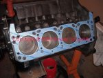
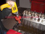
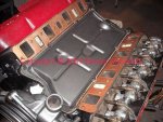
The block deck was cleaned one last time, then the head gaskets were stuck in place and checked that all penetrations are properly aligned.

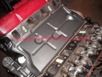
These are plain old fel-pro "permatorque" composition gaskets, no further attention will be needed.

When I tore this motor down, I found an oem steel shim gasket on one side, with a composition gasket on the other side! Typical po-virus kinda schnizz.
 

Attachments

  • Lifters In and Head Gasket.jpg
    Lifters In and Head Gasket.jpg
    86.1 KB · Views: 1,016
The heads and rocker assemblies have been installed.

One rocker assembly was reconditioned back in the beginning during the diagnostic phase, the other one has been freshly prepped recently.
 

Attachments

  • Heads On.jpg
    Heads On.jpg
    99.3 KB · Views: 997
With the motor flipped for the final time, bill knocked in the remainder of the soft plugs and installed the pan.
 

Attachments

  • Soft Plugs Installed.jpg
    Soft Plugs Installed.jpg
    93.4 KB · Views: 1,028
We did not install the lifter chamber cover (valley pan) at this point so that oil could be dumped in directly. This also allows a complete visual regarding oil flow to the lifter galleries when we run the pump off the drill motor.

The rocker assemblies were not "pre-oiled (even though they were put together with assembly lube) so that the slightest amount of oil flow could be observed once the rocker shafts filled.

After installing an oil filter and dumpin' in oil, the drill motor was cranked.

After lube system air was purged and circulation established, we're seeing 60+ psi just off the drill (about 1400 shaft rpm). That is with 15w-40 at an ambient temp of about 55f.
 

Attachments

  • Got Oil 2.jpg
    Got Oil 2.jpg
    53.9 KB · Views: 984
So...after more than four years (just livin' at our shop!) the bitch has finally gotta heart again!

Oil squirtin' from all the right places on the rocker assembly just like it's supposed to.

Since the nose of the motor is slightly low on the stand as compared to when installed in the rig, the drainback from the front sump is impeded. With six quarts of oil dumped in, the pump pickup started sukkin' air as the rear sump could not fill fast enough to keep up. Adding one more quart took care of that, so this is a perfect way of illustrating that a Scout II should always use seven quarts in the pan and scruu the dipstick reading!
 

Attachments

  • Lifters and Rockers Flooding.jpg
    Lifters and Rockers Flooding.jpg
    74.7 KB · Views: 1,021
My compliments to you, Mike and bill this motor is going to purr like a kitten with the teeth of a lion. Excellent post with pictures. I am sure sonja will be very happy.

Ron
 
I totally agree ron.
I've watched this story from the begining over 2 years ago.
I wonder if someone could publish the story. It certainly has well documented detail and fact; plus the agony of the pitfills of having to deal with the unscrupulous or the less than stellar shops. I'd buy 2 of 'em! There's lots of books on rebuilds, but this has the human interest edge to it.

Two years gone? How about four years as of this month!

Time flies when yore not havin' fun!

Life has happened over and over for all of us, this stuff dam shore ain't important in the big scheme of thangs. It's just time now to git this one wrapped and gone, they ain't gonna let me work in the parking lot at the assisted living unit I'm headed to.
 
I smiled when I saw the 'qa' marks on the rod bolts. I have observed seasoned builders fail to torque something, resulting in big dollar damage. Qa or as I call 'em 'witness marks' make sure things are right before you button it up.

Things are looking right good for that sonja motor.

Ray
 
We can see the finish line.

Here the lifter cover has been installed.

The gasket is stuck down with black 3m trim cement on both sides of the rubber/cork composite gasket.

3m was also used on the bolt threads. Even if the gasket actually seals on the really shitty machined block surfaces, oil will migrate past the bolt threads if they are not sealed.
 

Attachments

  • Lifter Cover Installed.jpg
    Lifter Cover Installed.jpg
    96.7 KB · Views: 877
Last edited:
The water tubes have been sterilized inside and out.

The replacement "o" rings are included in a complete gasket set.

The seats for the water tubes in both the water pump housing and in the heads must be carefully cleaned and the sealing surfaces burnished to bright metal. Any foreign material will prevent the "o" ring from doing it's job.

Once the "o" rings are installed in the water tube grooves, I slather 'em with hylomar to insure positive sealing.
 

Attachments

  • Water Tubes and O Rings.jpg
    Water Tubes and O Rings.jpg
    93.6 KB · Views: 867
The water pump housing, water tubes, alternator/ac compressor mount, and the ps pump mount have been installed.

The paint work will be touched up once the engine is hung.
 

Attachments

  • Tubes and Mounts.jpg
    Tubes and Mounts.jpg
    98.8 KB · Views: 887
Don't forget to install and tighten the water tube retainers on each head (or in the block if your motor is an "improved cooling" unit).
 

Attachments

  • Water Tube Retainer.jpg
    Water Tube Retainer.jpg
    67.8 KB · Views: 876
Many of these engines will have an a.I.r. Pump mount incorporated into the ps pump mount. That means...in order to r&r a valve cover, ya gotta remove the ps pump and the entire mount. That suks!

So...if the a.I.r. Pump on yore motor somehow turned up mia, then whack tha dam ear of the mount with a sawzall. Then neatly grind it so it looks factory. Or better yet...call up Jeff and order a rpt power steering pump mount that makes valve cover work ez:

rpt power steering pump bracket for IH v8 w/o smog pump - International Scout parts
 

Attachments

  • AIR Pump Mount Cut Down.jpg
    AIR Pump Mount Cut Down.jpg
    85.6 KB · Views: 884
Last edited:
The shim-type intake manifold gaskets should be treated to three tacky coats of a "coppercoat" type gasket adhesive...either the spray version or the dauber-inna-can version.

After spraying the last coat (fifteen minutes flash time between coats), carefully position each gasket in place paying close attention to the callout stamped on each regarding which side goes toward the manifold.
 

Attachments

  • Intake Gaskets Coated.jpg
    Intake Gaskets Coated.jpg
    61.2 KB · Views: 869
Last edited:
Here's the intake gaskets in proper position.

These gaskets are the oem type for gasoline-fuel engines. The "lpg" (propane) fuel versions have the heat riser segments blocked. I prefer to use those intake gaskets in work I do on my own stuff.

The most recent release of the fel-pro full engine gasket sets (not conversion sets) have all gaskets included (except head gaskets) for both 266/304 and 345 engines. Make sure that you use the correct intake gaskets, valley cover gasket, etc. If building a 266/304. This little detail would really scruu with sailor jerry's haid.
 

Attachments

  • Intake Gaskets In Place.jpg
    Intake Gaskets In Place.jpg
    116.5 KB · Views: 873
Forgot to take a shot of the intake maneefol installed...trust me, that fookin' 58lb. Chunka iron is mounted.

And...for insurance, ya seal all the threads on the intake bolts with hylomar since some of the holes penetrate the intake port.
 
Folks are always wantin' ta know how to determine which sv engine they got.

Here's a shot of the boss located just above the passenger side front engine support, and under the exhaust manifold.

This one shows 345e and then followed by the sequential engine serial number (not a vin!!!).
 

Attachments

  • Engine I.D. Boss.jpg
    Engine I.D. Boss.jpg
    71.8 KB · Views: 875
After drivin' in the rear core plugs, and then finalizing the position of the rear crank seal, it's time to mount the flex plate for the tf 727 slushbox.

First to go on is the clean hub spacer. It includes a large spring pin that engages a particular hole in the crank hub. This flex place/crank/harmonic balancer/internal reciprocating engine parts were balanced as a unit when the engine went down the transfer line at the factory. So the flex plate must be re-installed in the same orientation it was mounted when the engine was balanced.

An sv engine set up with a flywheel for a manual transmission does not use this crank spacer or the flex plate.
 

Attachments

  • Flex Plate Spacer.jpg
    Flex Plate Spacer.jpg
    71 KB · Views: 867
Back
Top