

You are using an out of date browser. It may not display this or other websites correctly.
You should upgrade or use an alternative browser.
You should upgrade or use an alternative browser.
Limited disassembly of a 1980 IC 196
- Thread starter Mark Pietz
- Start date
Mark Pietz
Member


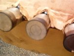
 although putting the turbo on is still a ways off, I thought I'd take the opportunity to actually put the turbo together. Admittedly, this is old technology, but it is simple technology and it is not difficult to rebuild a trw 300 series turbocharger. I have previously posted about the need to increase the flow of the original "b" flow to better match the increased cubes of the 196. The next size up trw was an "f" flow, but my graphing doesn't show it to be adequate either. So I am going to "mix and match" the "f" flow turbine with a rayjay "e" flow impeller. Without rehashing the logic of this (maybe later), an e flow compressor will give me the flow, while the f flow turbine will give quicker spooling and the e flow turbine, this to hopefully bring it on sooner with the relatively slowly turning IH engine. Towards this end, I had the original IH b flow housing machined to accept the e flow wheel, which is an accepted practice. So here are pics of a disassembled and thoroughly cleaned 300 series. I'll refer to what's going on in these steps relative to the procedures found in the GM corvair manual. No real special tools needed other than snap ring tools, a dial indicator, and a 0.001" resolution caliper, and oh - get an inch-pound torque wrench. The one in the picture I got off ebay for $25. Reads up to 300 inch-pounds.
 First pic - comparing b, f and e flow wheels (top left, top right, and bottom, respectively). Second - backside of machined compressor housing. Third is center housing that holds the guts - I've already drilled and tapped for a new oil feed - and various shims and snap rings, fourth is the new bearing, the dish holding the carbon seal, and more bits, and fifth is the f flow turbine and heat shield and spacing spring. In the baggie is the new "piston ring" seal for the turbine and a special plastic ring to compress it so it can slip into the center housing when the time comes. While this all looks confusing, it is really quite simple. The whole process is simply setting clearance for the bearing and then spacing for the impeller.
Last edited:
Mark Pietz
Member
]next step is determining the end play of the new bearing upon the turbine shaft. In my case, it came in around 0.005", where it should be. You put the bearing on the shaft and install the mating ring on top of it, which "traps" it as when installed. Endplay measured by sliding a feeler gauge between the bearing and turbine shaft shoulder.
Next you determine the end play of the bearing in the housing itself. You use shims between the large diameter of the bearing and the housing. You want 0.001-0.002"; I got around 0.0025", which is still okay. I determined this by putting in a shim, then bearing, and then installing the small snap ring, and sliding various feeler gauges in between the snap ring and the bearing to see how much play there was.
So now total end play - bearing on shaft, and bearing in housing - is around 0.008" so far so good.
I'll have to post the next series of pics tomorrow!
Last edited:
Mark Pietz
Member
The mating ring is oiled and placed on the bearing thrust surface, and then the carbon seal "dish", and seal, is pressed into place after putting a large, thin o-ring onto it. Then the big snap ring. A spacer is placed into the hole in the middle of it all, then the e wheel, housing gasket and three bolts snugged to 80 inch-lbs. Then the turbine shaft, without piston ring, is carefully put into position without securing it with the left-hand nut. The whole point of this is to use a dial indicator to determine the distance the impeller has between the center housing and the compressor housing. I had 0.033" this time.
What the IH turbo "manual" leaves out - and the corvair GM manual includes - is a simple example of how to determine the shim required for proper spacing of the impeller. In my case, you take 0.033" and subtract 0.008", which gives 0.025". Then you subtract 0.015" and 0.020" separately from 0.025". Then you get 0.010" and 0.005", respectively, which is a range. The answer is a shim between these two numbers. Since there are only two shim possibilities - 0.010" and 0.015", I select 0.010", which is the outside limit. I'll have a clearance of 0.015", which is the minimum. It's really not that complicated once you have the parts in hand and look at how it goes together. So I placed a 0.010" shim on top of the spacer and underneath the impeller.


What the IH turbo "manual" leaves out - and the corvair GM manual includes - is a simple example of how to determine the shim required for proper spacing of the impeller. In my case, you take 0.033" and subtract 0.008", which gives 0.025". Then you subtract 0.015" and 0.020" separately from 0.025". Then you get 0.010" and 0.005", respectively, which is a range. The answer is a shim between these two numbers. Since there are only two shim possibilities - 0.010" and 0.015", I select 0.010", which is the outside limit. I'll have a clearance of 0.015", which is the minimum. It's really not that complicated once you have the parts in hand and look at how it goes together. So I placed a 0.010" shim on top of the spacer and underneath the impeller.
Last edited:
Mark Pietz
Member
The piston ring is placed into the groove on the turbine shaft and the special plastic sleeve slipped over it so that the expanded ring won't snag (and ruin) itself and gouge the tight bore it rides in. In use, it does not rotate, but the shaft's groove rotates around it. It keeps oil out of the hot side. When you slide the turbine shaft "home", the plastic is forced off but isn't otherwise removed. When the turbo first operates, it will melt and blow away. I am not including pics of how the thick iron heat shield and special spacing spring is compressed so the turbine shaft can slide home, but one must be very careful with this step. I used a combination of 6" vice and a big c-clamp. Then the impeller is slid on....
The 5/16 - 24 nut that holds the impeller to the shaft is left hand, and torqued to 80 inch-lbs. The compressor housing's six bolts are likewise torqued to the same amount.
Most of these old turbo's turbine housings have been sand blasted, and that keeps the heat shield from compressing enough and it will then ride against the back of the turbine, which isn't a good thing. A special stainless steel ring is made to bring back the needed spacing, and is placed between the heat shield and the turbine housing. Then a special fiber gasket goes between the central housing and turbine housing, and the stylish v-clamp is torqued to 10 inch-lbs. I say stylish because this was the first clamp offered and shows in the parts books. Later production went "cheap" and a simpler band was devised. This happened to the corvair as well. Both IH turbos I acquired had the cheapie band, but I had an early style on hand.
this is the gist of how a trw 300 series turbo goes together, and isn't a complete tutorial. But if you actually do this yourself, follow the manual. I left out some pics and steps.
If I can do this, any one can. I'm also including some pics of what I started with in the next posting....
Last edited:
Mark Pietz
Member
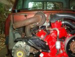
Getting these things apart in the first place puts you in one of two situations - lucking out where the turbine housing separates fairly easily - as mine did here after soaking the turbine cavity with penerating oil for many days and carefully applying heat with a propane torch, then - against all recommendations - carefully using large screwdrivers in strategic locations. Or...drastic measures. On one I actually had to use a sledge hammer and block of wood to get them apart, and it didn't ruin anything, but I was sweating bullets on that one. this on the advise of a pro.... You'll note lots of heavy carbon and varnish on some of these parts, which is in large part the result of what must have been bad valve guides and rings, as well as the natural result of having a 'wet', draw-through system.
A heat gun will sufficiently expand the impeller so a drill press can be used to press out the turbine shaft - gee, just like in the pictures. Then it is a matter of getting the snap rings out and cleaning the parts in the usual manner.
I included a pic of one I got that had gotten a lot of water in it. The insult to injury is that the p.o. Had rebuilt the thing and used a regular 5/16" right hand coarse nut to assemble it. It apparently lived a long time this way, but at the end of the day, few parts were salvageable on this turbo. A shame, as the b flow turbine shaft is popular in some quarters.


.jpg")


.jpg")
this on the advise of a pro.... You'll note lots of heavy carbon and varnish on some of these parts, which is in large part the result of what must have been bad valve guides and rings, as well as the natural result of having a 'wet', draw-through system.A heat gun will sufficiently expand the impeller so a drill press can be used to press out the turbine shaft - gee, just like in the pictures. Then it is a matter of getting the snap rings out and cleaning the parts in the usual manner.
I included a pic of one I got that had gotten a lot of water in it. The insult to injury is that the p.o. Had rebuilt the thing and used a regular 5/16" right hand coarse nut to assemble it. It apparently lived a long time this way, but at the end of the day, few parts were salvageable on this turbo. A shame, as the b flow turbine shaft is popular in some quarters.
Last edited:
Mark Pietz
Member
I know it's boring, but I need to get this thing running right and smogged. Kalifornia has its issues as we all know. Anyway, it hasn't idled as well as I had hoped, although when I had been doing test runs up and down my street, it seemed basically strong. But here I am now with all the smog stuff on it and finishing up putting the front clip on it. Recent activity is as follows in getting this very beaten 1980 "road worthy" although cosmetic problems such as crunched fenders and dents are at the bottom of the list.
1) turned new neoprene body bushings, 7/8" thick. Done.
2) new frame and spring eye rubber bushings (1 of the 12 from the vendor was wrong). Otherwise, suspension done this weekend.
3) front axle completely gone through. Done rebuilt power brake booster, new m/c, rebuilt calipers, turned rotors (last time for these guys), all new brake hoses, system flushed. Done
4) power steering. Pump cleaned, painted, resealed, except shaft seal leaks worse. Bad seal. Tried to replace high pressure hose, but there's an issue with listings and availability for the i4 application (not same as v8, as we found out!). Jeff looking into this...otherwise old hose still pliable and being used for now.
5) cleaned cooling system with prestone super flush + 1 lb. Citric acid powder, flushed out lots of rust from corroded lower hose spring. Installed new stainless steel spring (used on mustangs). Installed 7lb cap. Heater system rebuilt and working aok.
6) installed correct carb approved catalytic convertor (magnaflow #39006 - carb approved for 1979-80 Scout II 196, 304, 345. Has 2.5" inlet and outlet). Referee station said they would verify if they even had to crawl under there to see the number, so be sure it's mounted down so they can see it! Done
7) serendpitously found an nos gulp valve used on 79-80 scouts w/196 (did you know they were made by Holley?). Unbelievable! Welded up new bracket to mount smog pump on left side of engine (above p/s pump) so I can have my air conditioning, eventually. Looks almost factory. Emissions air hoses lengthened to accomodate this change. Does work! When you run the engine up and let off the gas, it takes a second or two to cycle; mild popping from tailpipe is proper response.
8) still need a proper tvs to control the egr. The one in there has broken nipples (sounds painful ). Egr in place, not operating yet.
9) smog pump. The pump "on loan" is failing and howls. However, it isn't a pump from a 1980. That air pump has a different number and sss is researching the difference, so it will be good to know exactly what parts ended up being goofy for the 196s the very last year. It May, in fact, be the same as the earlier pumps with the exception of, say, having metric threads or somesuch - one can hope. There are absolutely no listings or availability for this pump otherwise. Period. Not wanting a smog nazi issue here. Sss to verify and then we'll see if a generic Scout air pump will substitute and pass the visual.
10) carb does backfire occasionally when blipping throttle. The backfire is sufficient to kill the engine (most of the time) or if not, it chugggggs and recovers. Don't know cause yet. Not happy with idle quality. The carb has been dicked with in the past but 1940s are rare birds and $$$$. Don't want to replace if it is avoidable. New fuel pump puts out a rock-steady 5 psi regardless.
11) took off the visible parts of the megajolt/edis system to get by the smog nazis. Reinstalled original prestolite distributor and timed per the emissions sticker. 0 btdc. Although the vacuum can does work and holds vacuum, for some bizarre reason I don't see its action reflected on the timing marks (using a timing light). Bizarre. Plus it is hooked to manifold vacuum all the time, per the sticker. Hmmm.... Further investigation required. In the meantime, I disconnected it to establish what the built-in mechanical curve is at this time. At 3,000 rpm I get 23 degrees. wow, is that late! Don't have the nerve yet to run the engine to 4k to see what it will do. I would like to know what the curve for that distributor is supposed to be. Can't be that late, can it? Update: obtained the three data points for this distributor. Appears the curve is low by at least 4 degrees at all points below 3,000 rpm. Looks like I'll be tweaking the primary spring post...in this distributor there's a light spring which controls advance up to around 3,500 rpm, then there's a heavier spring that retards the rate Of advance after that point and pushes the advance curve downward (done this once before on this type of distributor).
Engine is otherwise sound, compression test puts all cylinders within 5 lbs., and it pulls 15 1/2 inches vacuum at idle.
Any comments/observations welcome at this time!
Getting closer to getting it on the road!
Update: took the vacuum canister apart, and then back together. Vacuum advance action now works; I get 8 degrees advance (crank) with it. I believe the little arm was misaligned somehow. About the backfire situation while blipping the throttle. Nothing made sense, except that the vehicle sat for a couple of months, and thinking maybe a small amount of water condensed in tank. Put in two bottles of heet, which is essentially methanol. The backfiring disappeared. Only backfires now if I'm blipping it too quickly and the gulp valve hasn't had time to cycle (as this leans out the intake manifold). Replaced rear wheel cylinders - one filled solid with rust and crud - new shoes, cleaned all hardware and return springs. Automatic adjusters working like champs. Rear axle seals don't appear to be leaking. Replaced all wheel cylinder and caliper bleed nipples with those special spring-loaded self bleeders. One was defective - they left out the guts! Napa replaced...however, one of the remanned calpers has a bad or goofy bleeder seat, and the special bleeder won't seat and seal, so replaced with stock nipple. Oh well....pedal goes low, so I'm thinking of adding a 10 psi check valve to the rear line.
Update to the update: the rougher-than-expected idle quality has really bugged me. So when you go through the process of excluding causes, you eventually get way down the list of possibilities. To this. When I put this back together, I took out of a box the two original motor mounts I had been saving from a time when I rebuilt them for the light line and sss sold them back in the 1990s. They were potted from urethane. My originals - to prove the process - were made from a batch of about shore a, 90 durometer, stuff. Later ones were from I think 70, which is a big difference, and the heavy mass of the sv engines worked well with them. Didn't occur to me how stiff these would be - especially with a much lighter 4 banger - and they transmitted almost all engine vibrations. The cab, having virtually no interior deadening materials (carpet or jute, no door panels), just the bench seat, was like a tuning fork and the needles on the gauges would just dance. I had a pair of oem mounts with still a bit of good rubber, and just put them in (those are actually a durometer of around 55). About 1/4" clearance left shell-to-mount, which is like the old saying "putting on your cleanest dirty shirt". Almost all the objectionable cab vibration and engine roughness simply went away. A bit of playing with the idle and wow! Eventually having a full interior will make it just like it had ought to be. Becoming more civilized a step at a time.
1) turned new neoprene body bushings, 7/8" thick. Done.
2) new frame and spring eye rubber bushings (1 of the 12 from the vendor was wrong). Otherwise, suspension done this weekend.
3) front axle completely gone through. Done rebuilt power brake booster, new m/c, rebuilt calipers, turned rotors (last time for these guys), all new brake hoses, system flushed. Done
4) power steering. Pump cleaned, painted, resealed, except shaft seal leaks worse. Bad seal. Tried to replace high pressure hose, but there's an issue with listings and availability for the i4 application (not same as v8, as we found out!). Jeff looking into this...otherwise old hose still pliable and being used for now.
5) cleaned cooling system with prestone super flush + 1 lb. Citric acid powder, flushed out lots of rust from corroded lower hose spring. Installed new stainless steel spring (used on mustangs). Installed 7lb cap. Heater system rebuilt and working aok.
6) installed correct carb approved catalytic convertor (magnaflow #39006 - carb approved for 1979-80 Scout II 196, 304, 345. Has 2.5" inlet and outlet). Referee station said they would verify if they even had to crawl under there to see the number, so be sure it's mounted down so they can see it! Done
7) serendpitously found an nos gulp valve used on 79-80 scouts w/196 (did you know they were made by Holley?). Unbelievable! Welded up new bracket to mount smog pump on left side of engine (above p/s pump) so I can have my air conditioning, eventually. Looks almost factory. Emissions air hoses lengthened to accomodate this change. Does work! When you run the engine up and let off the gas, it takes a second or two to cycle; mild popping from tailpipe is proper response.
8) still need a proper tvs to control the egr. The one in there has broken nipples (sounds painful
9) smog pump. The pump "on loan" is failing and howls. However, it isn't a pump from a 1980. That air pump has a different number and sss is researching the difference, so it will be good to know exactly what parts ended up being goofy for the 196s the very last year. It May, in fact, be the same as the earlier pumps with the exception of, say, having metric threads or somesuch - one can hope. There are absolutely no listings or availability for this pump otherwise. Period. Not wanting a smog nazi issue here. Sss to verify and then we'll see if a generic Scout air pump will substitute and pass the visual.
10) carb does backfire occasionally when blipping throttle. The backfire is sufficient to kill the engine (most of the time) or if not, it chugggggs and recovers. Don't know cause yet. Not happy with idle quality. The carb has been dicked with in the past but 1940s are rare birds and $$$$. Don't want to replace if it is avoidable. New fuel pump puts out a rock-steady 5 psi regardless.
11) took off the visible parts of the megajolt/edis system to get by the smog nazis. Reinstalled original prestolite distributor and timed per the emissions sticker. 0 btdc. Although the vacuum can does work and holds vacuum, for some bizarre reason I don't see its action reflected on the timing marks (using a timing light). Bizarre. Plus it is hooked to manifold vacuum all the time, per the sticker. Hmmm.... Further investigation required. In the meantime, I disconnected it to establish what the built-in mechanical curve is at this time. At 3,000 rpm I get 23 degrees.
wow, is that late! Don't have the nerve yet to run the engine to 4k to see what it will do. I would like to know what the curve for that distributor is supposed to be. Can't be that late, can it? Update: obtained the three data points for this distributor. Appears the curve is low by at least 4 degrees at all points below 3,000 rpm. Looks like I'll be tweaking the primary spring post...in this distributor there's a light spring which controls advance up to around 3,500 rpm, then there's a heavier spring that retards the rate Of advance after that point and pushes the advance curve downward (done this once before on this type of distributor).Engine is otherwise sound, compression test puts all cylinders within 5 lbs., and it pulls 15 1/2 inches vacuum at idle.
Any comments/observations welcome at this time!
Getting closer to getting it on the road!
Update: took the vacuum canister apart, and then back together. Vacuum advance action now works; I get 8 degrees advance (crank) with it. I believe the little arm was misaligned somehow. About the backfire situation while blipping the throttle. Nothing made sense, except that the vehicle sat for a couple of months, and thinking maybe a small amount of water condensed in tank. Put in two bottles of heet, which is essentially methanol. The backfiring disappeared. Only backfires now if I'm blipping it too quickly and the gulp valve hasn't had time to cycle (as this leans out the intake manifold). Replaced rear wheel cylinders - one filled solid with rust and crud - new shoes, cleaned all hardware and return springs. Automatic adjusters working like champs. Rear axle seals don't appear to be leaking. Replaced all wheel cylinder and caliper bleed nipples with those special spring-loaded self bleeders. One was defective - they left out the guts! Napa replaced...however, one of the remanned calpers has a bad or goofy bleeder seat, and the special bleeder won't seat and seal, so replaced with stock nipple. Oh well....pedal goes low, so I'm thinking of adding a 10 psi check valve to the rear line.
Update to the update: the rougher-than-expected idle quality has really bugged me. So when you go through the process of excluding causes, you eventually get way down the list of possibilities. To this. When I put this back together, I took out of a box the two original motor mounts I had been saving from a time when I rebuilt them for the light line and sss sold them back in the 1990s. They were potted from urethane. My originals - to prove the process - were made from a batch of about shore a, 90 durometer, stuff. Later ones were from I think 70, which is a big difference, and the heavy mass of the sv engines worked well with them. Didn't occur to me how stiff these would be - especially with a much lighter 4 banger - and they transmitted almost all engine vibrations. The cab, having virtually no interior deadening materials (carpet or jute, no door panels), just the bench seat, was like a tuning fork and the needles on the gauges would just dance. I had a pair of oem mounts with still a bit of good rubber, and just put them in (those are actually a durometer of around 55). About 1/4" clearance left shell-to-mount, which is like the old saying "putting on your cleanest dirty shirt". Almost all the objectionable cab vibration and engine roughness simply went away. A bit of playing with the idle and wow! Eventually having a full interior will make it just like it had ought to be. Becoming more civilized a step at a time.
Last edited:
Mark Pietz
Member
Sh*t. I have a flat lobe. The pushrod, fourth from left (intake?) does not turn, regardless of rpm. This is the one that always turned a bit slow. Now it stopped. And I had just changed the oil!
Mark Pietz
Member
I'm pretty disgusted at this point, and I won't fool myself thinking there's an easy fix. We identified this was a slow turner from the get-go, now it stopped, as rk thought it might. Funny thing is that I was at IHPA yesterday and the topic of cams going flat had come up.
If it was turning, albeit slowly, and now isn't, my money is on the fact that the lobe was only marginally "tilted" right and then quickly wore down. All lifters and half the pushrods were new, and I thoroughly pre-lubed the lobes, etc. The rest turn merrily along….
Unless tinker bell sprinkles magic dust on that 196, I foresee removing the radiator, everything bolted to the front of the engine, the rocker shaft, pushrods and lifters, and then pulling the shaft itself. Crappy when I think I just finished putting the entire front clip back on and all was buttoned up and ready to drive down the hill to have it smogged. No point in that now. I'll wait for rk to weigh in, but I think that's the lay of the land.
FDChappie
Well-known member
Yea, I here you and I can see you've made every attempt to do a first class job. I don't know if this helps or not, but persistence usually pays off.
If it makes you feel any better the 345 in my Scout has developed a pretty consistent lifter tap and I think it's loosing a lobe too. But I really can't complain as I've got $50 in the short block and have been driving it for over 10 years.
If it makes you feel any better the 345 in my Scout has developed a pretty consistent lifter tap and I think it's loosing a lobe too. But I really can't complain as I've got $50 in the short block and have been driving it for over 10 years.
Mark Pietz
Member
Yeah, discouraging. I had a 1975 xlc with a 345 that I drove for 17 years (!) and the original engine went 400k before a cam bearing went away. And I ran it on fram filters, and even for a while, reclaimed oil from walmart. (I suspect that back then the zddp level was still superior than today's oil). Quiet and pulled strong even to the end.
I've had this project truck for over four years (two of them with it on blocks in the garage) and was getting soooo close to actually getting it on the road.
I've had this project truck for over four years (two of them with it on blocks in the garage) and was getting soooo close to actually getting it on the road.
Robert Kenney
Super Moderator
Mark, sorry to hear about your situation.
Might I ask which cam you have and who ground it? First thing I'd do is pull that lifter and look at the pattern on the face. Also look at the lobe. The taper should be obvious by the wear patern and witness marks..
Two things that come up in my mind with these sv's
1) huge lifter to bore clearance. .003+ factory new.
2) lobe taper used in the industry is .001-.002"
with the large clearance we can assume that the lifter can rock enough to negate the lobe taper if only .001".
The industry standard is to have the taper with the large/high point to the rear to make sure the cam is sucked back into the block and not spit out the front, as most engines don't have a retainer plate like the sv series and must be kept in place.
Mark I thought you looked at the lobe location in relation to the lifter bore. I have not looked for your posted info yet so you can relay what you found. If the sv location offset is not all the same way, and the taper is all big to the rear, some lifters
won't want to rotate as easily as others...
Scooter
Active member
If you have a need for a used whooped 152, I have one sitting here in my cave taking up space. I don't have a use for it what so ever. It's a huge boat anchor sitting off in the corner waiting for some one in need. Not sure if any of the parts would work for the 196. Just thought I offer it if needed
Mark Pietz
Member
Robert,
I won't be able to have some of the answers for a week or two, as I'm going to be out of town on business and can't get to pulling parts right now.
Regarding lifter bores, that wasn't something pointed out to look at during the rebuild! So I don't even know what to say at this point, other than the lobes on the cam didn't look worn through and the engine did run very quietly.
I gave the cam to Jeff here at IHPA, so it was whoever he trusts to do it. Lifters were new, also from Jeff, and I replaced half the pushrods just because. All rocker arms were new. You saw the initial fire-up procedure.
As soon as I can I'll pull the rocker arm assay and pushrods, and then that particular lifter. I'll look down that hole and report back what I see (just tell me what I should be looking for), but in reality, where do I go from here other than pulling the cam and fixing things somehow. What's the next step? Another regrind? I understand what you're saying about taper and desired end-thrusts of a camshaft (wasn't it once considered to have half the lobes tapered one way and the others the other way to "neutralize" thrust?) what can be done differently to fix this problem? I certainly don't want to pull that engine. I certainly don't want another headache after four years of d*cking with this and being so close to driving it! Projects do lose their luster after time and setbacks. Just venting from frustration.
Mark Pietz
Member
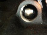
Here's a pic of the #6 lifter from the front, and a shot down the hole (crummy camera) during the initial tear-down a few years ago. This was the only lifter/lobe that looked out of the ordinary upon disassembly. Doesn't help now, but anyway…
I'll try to get to pulling that lifter today.
I'll try to get to pulling that lifter today.
Attachments
Mark Pietz
Member
if you have a need for a used whooped 152, I have one sitting here in my cave taking up space. I don't have a use for it what so ever. It's a huge boat anchor sitting off in the corner waiting for some one in need. Not sure if any of the parts would work for the 196. Just thought I offer it if needed
Thanks, scooter. I might need that cam! I believe the fours are all the same (except for the 152s having a cam for the fuel pump but that's not needed on a late ic 196).
Scooter
Active member
thanks, scooter. I might need that cam! I believe the fours are all the same (except for the 152s having a cam for the fuel pump but that's not needed on a late ic 196).
No problem. I saved this 152 after doing a motor swap for some one about a year ago. After having a talk with Jeff up at IHPA, with ordering parts for myself we got to talking about that motor, and he suggest saving at least the came from it since apparently there isn't any after market replacements for these IH 4 poppers. So there sits the 152 off in the corner of my cave collecting dust. I just haven't had time or energy to do anything about it. If you need it, let me know, and I'll let you have first dibs on it. Otherwise, I will pull it and send it up to Jeff, maybe.
Mark Pietz
Member
Thanks! Let's hold off till we know what needs to be done! I just now pulled the rocker arm shaft, pushrods, and that lifter. I pulled the one next to it also for comparison, since if there's something subtle I don't see, then there's that one. Here's what I see. There is a concentric ring on the bottom of the lifter #5 (fifth from the front). It is still like glass and does not catch a nail. I pulled the one next to it, #4. The appearance is otherwise identical save for that ring. Both bottoms have a very faint outer band to the edge (about 3/16" wide) that looks like exceedingly fine radial marks, almost like scuffs. Looking down the holes they look okay from two feet away but that doesn't mean anything. Can't get any closer. I wiped the bottoms of the lifters dry and put them together and there is the slightest rocking, so I'm guessing at least one of them had that arc ground into them.
Right before I pulled this apart I warmed it up and again watched the pushrod action. #1 and 2 actually spun backwards from the other six! (ccw) so the tilt on those was ground opposite the others (cw), for some reason, or perhaps by intent, I wouldn't know. A couple turned slowly, but I'd say still okay, some others somewhat faster (this at a slow idle). At around, say, 1500 rpm the rotations were what I'd say were okay, not spinning like tops but turning well enough. Except for #5, nada. Just stuck there. I suppose (wishful thinking?) that it is possible that the lifter was turning beneath the pushrod end, but that's wishful thinking. I don't believe it happens that way.
Here's the pic. Can't get a better shot.
Next Monday afternoon I'll be passing by laverne. I could always let Robert take a look at the lifter if he was so inclined.
Mark Pietz
Member
The previous post wouldn't let me post a pic. Darn glitch…
I had also thought that perhaps the different pushrod ends could have been a factor. There are those with ball ends and then the others with more of a bullet end. #5 was bullet ended, but others with those were turning okay.


I had also thought that perhaps the different pushrod ends could have been a factor. There are those with ball ends and then the others with more of a bullet end. #5 was bullet ended, but others with those were turning okay.
Last edited: