Limited disassembly of a 1980 IC 196

I do not recommend much heat. The risk of warping the block is high.

You are having the typical problem I have. I jigged and used a surface grinder to square up a 3/8 socket allen. Perfectly fitted to the odd plug. I still struggle and they still round out.

The plugs are soft and after a life of being threaded in I usually have end up step drilling 50 % them out and picking the remaining threads out. ..

the welch plug can be inverted by denting the middle in at the center or drive a punch through it . it will retract and come out easily..
 
I do not recommend much heat. The risk of warping the block is high.

I agree. I use an acetylene flame and keep the heat localized on the plug (or bolt, or whatever). I think the wax is what really does the trick.
But for sure, torch flame on anything carries some risk.
 
I used a small propane torch and kept it on the square protrusion, so I don't think I warped anything. That location on the block is quite thick, so should provide a bit of meat for tapping if drilling doesn't go perfectly.

Regarding that large plug in the back with the weird hole. I'll put a bit of heat on it to see what happens, but probably will have to resort to the drill.
 
Update:
got the weird oil galley plug out of the back of the block. 5/16" square. Ground a 1/2 to 3/8" socket adaptor to fit, and a little heat. It's out.
Got the funky rounded off 1/8" pipe plug out via step-drilling and heat. That long passage was filled with sludge resembling permatex #2.

Took everything to the machine shop Tuesday, just got the results this morning.

1) crankshaft miked out within standard specs and will (or he did) polish it. Need main and rod bearings.
2) pistons: block wasn't worn badly, and 0.020"s will work, May have to go 0.030" if availability is a problem with the silvolites. Jeff working on that.
3) piston rings: I've used moly in the past; Jeff suggests iron. Boost will be intermittent and probably limited to 5 lbs or so. Concern is durability? I'm open here...
4) deck. Machine shop said it was flat, so that's that.
5) cam bearings: Jeff sourcing those.
6) camshaft: will get to Jeff to send out for a regrind. Application has been stated here previously. Appreciate specifics.


The head is sitting on my workbench. Need to finish disassembly and grind out smog bumps before sending it down for work. I can detect that some exhaust valves feel loose in their guides. I see on this board that available exhaust guides May be problematic in getting best fit for valves? Best solution for that? Will have the head checked for cracks and flatness. I'm wary of old springs. Since I don't plan on running the engine over 4,000 rpm, and then rarely, could go with oem springs.
 
Update:
3) piston rings: I've used moly in the past; Jeff suggests iron. Boost will be intermittent and probably limited to 5 lbs or so. Concern is durability?
Not that Jeff is wrong but my personal opinion is that anytime I build an engine that will move toward more heat and loading I run a moly top ring. Even intermittent short term heat and high loading can increase top ring wear. You May be fine but what is the added cost really? Make sure you run proper end gaps on that top ring (.018 +). 5 pounds is going to make the dynamic compression ratio 11-1(8.25 x 1.33) so plan for that on this build

6) camshaft: will get to Jeff to send out for a regrind. Application has been stated here previously. Appreciate specifics.

Isky 190156 grind and lc applied to your cam .

The head is sitting on my workbench. Need to finish disassembly and grind out smog bumps before sending it down for work. I can detect that some exhaust valves feel loose in their guides. I see on this board that available exhaust guides May be problematic in getting best fit for valves? Best solution for that?

The exhaust guides take it in the azz on these due to the rocker geometry.
Silicon bronze guides only for this application .002-.0025 clearance. Don't use the so called pc type of seal.

Will have the head checked for cracks and flatness. I'm wary of old springs. Since I don't plan on running the engine over 4,000 rpm, and then rarely, could go with oem springs.

Don't use the original springs. I recommend the comp spring that is available from Jeff. Set it up @ 1.850. That will yield 80-85# seat. That is enough for your application. Forced induction is always trying to blow the intake valve open so you should run more than what you think. Valve area x manifold pressure peak is the increase in seat pressure you should run.
 
Wonderful progress.

Block is done. Bored 0.020" over, plateau-honed, and the silvolites fitted up
cam bearings set
got the camshaft ground to isky 156 specs. (0.050" ground off base circle so May need custom pushrods?)
timing gears were in excellent shape.
Crank polished and got the new main and rod bearings.
Flywheel surfaced (ground).
Rebuilt clutch kit from Jeff
crank, front pulley, rods, pistons, flywheel and pressure plate just back today from the balancer.

Will pick up all from moore's on Friday.
Curious to inspect the cam bearings and accuracy of oil hole alignments. Hopefully won't have to complete by drilling like I had to do once in the past.

Should begin begin assembling the "short block" in the next couple of weeks, then vacation. :icon_up:

bell housing, front cover, tappet cover, oil pan, intake manifold all tanked, cleaned, and painted. Drain plug bung welded into front sump of oil pan. Need to weld in 1/2" npt drain bung to tappet cover for turbo drain.

Headwork will have to wait until late August.
 
Got the block up on the engine stand. In the process of getting the block bored and plateau-honed, the issue of clearance wasn't really addressed. He did a great job and the clearance between the piston skirts and bores is 0.0035". Although that is the spec in the IH manual and the lower end for what hastings recommends for the svs, I hope that won't be too tight with some limited boost. I can always take it back to increase it (he won't be happy with that) if it would be a real issue.

The rotating assembly was balanced. A sheet came along with it with the weights of various parts. I'm not certain how to interpret some of the annotations. You can see where weight was ground off some of the rods and the crank throws.
 
.0035 is good for your application. Also where I set up my 152 t project.

Just watch oil temps like a hawk so piston temps are in control.
 
This engine should not have a cooling problem. It is set up with a 3-row radiator (essentially the hd cooling system for a 345 w/towing package), plus whatever internal advantages May come from it being an ic engine. But for peace of mind add a small oil cooler with a thermostat to permit flow to cooler when 190 degrees is reached?

I noticed that a stock 152 specs for 0.0025", so you added a thou. By nature do bigger bores need a bit more clearance?
 
Yea, add a large plate stack oil cooler and thermostat. Use 180 as a keep at temp. Must use a stat for the oil cooler as cold is as bad as hot.

My 152 was built with the intension's to turbo charge so I clearanced the bores and rings accordingly.
 
Robert,
some advice on this situation. I have the engine block turned over and the main caps removed. The machine shop lined up the holes in all the cam bearings perfectly. That's the great news. But the very odd thing is this. The holes in the webs that feed oil to the mains and cam bearings are slightly larger than 7/32". The oil holes in the cam bearings for 1, 2, 3 and 5 are likewise this diameter as I can pass a drill bit this size completely through. What caught my eye was the hole in the cam bearing for #4. It was visibly smaller, so I sized it. A 9/64" bit just passes through it. #4 also ultimately feeds the rocker shaft. Why would the hole in #4 be smaller than the rest? It's actually just as wide as that arc/groove on the inside of the bearing surface it intercepts. Should I drill this one out to match the rest?
 
Opinions vary but I leave the bearing hole diameters alone so long as they are not overlapping and partially blocked.. Never had a problem with rocker assembly oiling.
On another note, only 2, 4 and 5 do more than oil the cam bearing 2 and 4 also supply oil to the valve train as you know. Drilling it to match #2 is your call. Suppose it can't hurt to match the two. Just make sure you deburr the drilling trash and don't let the drill jab the other side of the bearing. :icon_xp:
 
Last edited:
Now that vacation is over and got things under control at the day job.

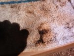
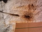
In spite of what anyone says, no one can be responsible to ensure engine cleanliness unless you do it yourself. Machine shop tanked engine 2x and said "absolutely clean, don't need to do any further cleaning", so I took delivery of block in a big plastic bag. Couple of days ago removed all the oil galley plugs, and the little one at the front end that caps the tappet galley. Well, well, well. An inch of crud and grit lurking behind that one. Also found a deposit of crud up inside the block; a wipe with the finger brought it back covered in black soot. Ironically the machine shop advised me to clean the crank 'cause the balancers don't do a good job of that. In running the brush into the holes, found some oil passages had significant grit in them. So a word to the wise. Don't take anyone's word for it. :hand:

got the head disassembled on Sunday and will hopefully grind out the smog humps this weekend, then get it over to the machine shop. The backside of intake valve #2 had a 1/4" thick deposit of carbon on it. Talk about a restriction. Two of the exhaust valves were wobbly. How does one assess the exhaust valve rotators?

The 0.020" over moly rings arrived, courtesy of northern auto parts.
 

Attachments

  • Crud in passage (Small).jpg
    Crud in passage (Small).jpg
    72.2 KB · Views: 528
  • Crud in passage 2 (Small).jpg
    Crud in passage 2 (Small).jpg
    56 KB · Views: 527
Last edited:
Some questions about grinding out the smog bumps. My head is drilled and tapped for a smog air rail, which had been removed sometime in the distant past. The #3 cylinder had a factory plug installed (still in there and I can't get it out) 'cause later rails only used three tubes. So last night it was fairly easy to grind the humps on those three down to "flush". So there are now three oval holes in the port's roof. I guess that's ok, that won't affect exhaust flow? Tonight I'm going to grind down the one with the factory plug in it and I think I'll end up with that port roof being fairly well flush with no real hole 'cause that plug projects into the port and will be ground down flush.

So should I get three factory plugs and grind them flush and install to try to have port roofs fairly flush, or try to remove the plug I am about to grind, and just have regular short plugs and port roofs with the holes?
 
I discovered I have three of the long plugs, so why not get the fourth and grind them flush. Since I'm committed now, of course no going back if one needed to install an air rail. The meat those teeny air tubes get wedged against, is gone. I was surprised how quickly a bump can be ground down, a little over 10 minutes. So next week off the head goes to get new valves, etc.
 
I'll be taking this head to the machine shop next week. I did follow some of the threads here about valves and guides. Are the silicon bronze guides hard to find, or is that something my shop should know about? If not, where would I direct him? My guess is that at a minimum I'll be buying all new exhaust guides and valves. We'll see where the intakes shake out.
 
Head dropped off at the machine shop today. I specified that I wanted the silicone bronze guides in the 0.415" size and stressed that they were available. After looking further into their books, they found a listing that matched the specs I found elsewhere here. So....as long as they can actually get them. He's going to tank the head and do all the measurements, but in the end, I want to replace all the exhaust parts, at a minimum. A fair bit of wobbling on at least two of them. Not that anal about the intakes. He did mention that it was his practice to set the exhausts up at 0.002", so that's good. Getting closer to getting this thing put together. :icon_wink:
 
.002 is a bit tight for a truck engine but so long as he hones not just reams the guide id to a nice finish .002 is ok.
 
I guess I'm a little confused here. Looking over Jesse b.'s thread from a couple of years back plus what's been posted here earlier, I thought 0.002" would be ok, and that's what the shop was inclined to do. As he hasn't done this yet I can call him Monday and tell him 0.0025" for the exhaust if that's safer. Intakes should be 0.0015 - 0.002"?

I did get a call from him Friday afternoon about the head. It needs to be surfaced slightly (good - it will be flat after that), and he's getting those correct silicon bronze exhaust guides and all new exhaust valves. One intake valve needed to be replaced, too. So I have one chance to have him do it however it is recommended here to do. I think Jesse b and I are using the same shop but having different experiences.

Washed the block yesterday. I don't care how great they say those machine shop washers work or how many times through they ran it. I brushed crud out of the oil galleries that would have gone straight to my bearings.
 
Head is done. Now the assembly can begin. I do have the factory manual sitting here, but just a couple points to clarify.

1) main and rod bearing shells. Should those be absolutely clean on the backside when pressing into their respective cavities, or should there be a thin coating of oil between the shells and the block webs and rods?
2) threads for rod bolts and main cap bolts get oiled. I read this as a "yes", just confirming.

Got the rings. Will set the top ring gap to 0.020"

had contacted arp a few months ago and the guy there never followed up on matching up some studs, so I need to call them again.
 
Back
Top