I-4 and SV Engine Non-Oiling Rocker Assembly

It is not imperative to use those bolts with the nylon pellets. You do need to use either the oem washers or use replacement thick grade 8 (hardened) washers between the bolt heads and the soft aluminum rocker stands.

Any replacement 5/16-18 x 3-1/4 grade 5 bolt will work. I have a box of 50+ on my bench now, all clean/used ones. Do not go any longer than 3-1/4" in length or you risk a bolt bottoming in a blind hole that was not tapped deep enough at the factory, the proper length is 3-1/4".

You must use something like hylomar or permatex #2 on the threads of the bolts which penetrate the cylinder head ports, otherwise oil will be pulled into the combustion chambers and four cylinders will smoke...and you will have four vacuum leaks as well.

The bolts should be snugged up in a "cris-cross" pattern, bringing the rocker stands slowly into contact with the head surface. I do this without the pushrods in place. I have a home-brew tool that I then use to lever the rocker arm against the valve spring, and engage each pushrod in turn.

Once all the bolts are snugged, then tighten each with a 8" ratchet, if you use standard torque for that size bolt, you May crack the aluminum rocker stand. If you use a torque wrench for doing this, then set it for no more than 12ft./lbs.
 
Do you use the nylon pellet bolts? If so where do you get the new nylon from? How much for some bolts? The washers apear to be oem. But bolts are just standard hardware. They are correct length @ 3 1/4" from bottom of head to tip of threads.
With a 1/8" thick washer. I have 5 stands per head so need 10 total. Thanks
 
On page 3 after you complete the first round of running the oil pump it states you rotate the engine backwards 10 rotations.

Just curious, what is the purpose of rotating it backwards vs forwards?


in order to try and keep all resources regarding the topic of this thread in one place, I'll re-post a document I've prepped (it's in draft form and has not had the jpegs embedded) regarding how to treat these motors that have been sitting non-rotated for several months/years.

The whole idea here is to prevent wiping out the cam bearings during initial dry-start rotation of the crank/cam shafts. Much of the time, the cam bearings in these engines are not damaged going in, but will quickly fail if a proper pre-lube procedure is not performed. All it takes is about three rotations of a "dry" cam that has "stuck" to the babbit layer of the cam bearing to wipe 'em out. From that point on, it's all down hill, no way to go back and "fix" anything except for replacing the cam bearings with new!
 
do you use the nylon pellet bolts? If so where do you get the new nylon from? How much for some bolts? The washers apear to be oem. But bolts are just standard hardware. They are correct length @ 3 1/4" from bottom of head to tip of threads.
With a 1/8" thick washer. I have 5 stands per head so need 10 total. Thanks

We don't have any new bolts with the nylon pellet. The ones we do have are reclaimed from engines that we part out and recondition the usable parts.

As for cost of used ones, contact Jeff at IH Parts America/530-268-0864. If he doesn't have a set of 10 nice ones at his location, I will dropship from my location. I should have a full set that actually have the IH logo on the head, but not all of 'em over the years had that designation. These were originally black oxide finish.

Do I personally use the "pellet" bolts? Sometimes, if I have a full set. But I'm not anal about that, I normally do not re-use much of the hardware on these engines other than the stuff that is somewhat special. Your motor will never know it doesn't have "pellet" bolts holding it's rocker stands down, but it will know if ya don't seal 'em!
 
Last edited by a moderator:
on page 3 after you complete the first round of running the oil pump it states you rotate the engine backwards 10 rotations.

Just curious, what is the purpose of rotating it backwards vs forwards?

Good question! No one has ever asked about that "10 turns backwards"!!

The reason...I'm anal about this stuff since we've seen so many engines destroyed by cranking over with the cam journals "stuck" to the cam bearing surfaces. I want to create a lubricating oil "wedge" between the journal and the bearing, just like the oil wedge that forms when the crankshaft is rotating at speed. That is standard practice when dealing with "friction"-type bearings such as the cam bearings in these engines. A "friction bearing" is one that has no rolling elements incorporated in it's design.

Since at that point we've run the oil pump for an extended period and hopefully fully flooded the rods/mains/lifters/cam bearings/rocker shaft assembly, we wanna spread the oil wedge across all the flat bearing surfaces so that when we do fire the motor off, it will be fully lubed as well as possible. Not as good as doing "assembly lube" when we build the motor, but next best thing!

By rotating backwards, we are spreading the oil wedge all around the bearing/journal circumference (I hope!) in the opposite direction from the direction the wedge forms when the engine is running, we're simply doing the best we can without pulling the main and rod caps to slime the journal/bearing interface, same for the cam journal/bearings.

The 10 rotations is just a judgment thing to make you think what is occurring and not rush to fire the motor in your excitement after determining that it is oiling and does have oil pressure!!

Thanks for bringing this up, it reminds me that I need to go back into that document and complete it with the embedded pics!
 
Well that makes good sense. I appreciate the answer.

Also, I am in the process of following the document. I am up to the point of the the 10 backwards rotations. I also do not have oil on the valve train yet. But I do have 50 psi. I am hoping it shows up after the rotations.

I will take your advice not not dispair just quite yet...

Thanks again.


By rotating backwards, we are spreading the oil wedge all around the bearing/journal circumference (I hope!) in the opposite direction from the direction the wedge forms when the engine is running, we're simply doing the best we can without pulling the main and rod caps to slime the journal/bearing interface, same for the cam journal/bearings.

The 10 rotations is just a judgment thing to make you think what is occurring and not rush to fire the motor in your excitement after determining that it is oiling and does have oil pressure!!

Thanks for bringing this up, it reminds me that I need to go back into that document and complete it with the embedded pics!
 
well that makes good sense. I appreciate the answer.

Also, I am in the process of following the document. I am up to the point of the the 10 backwards rotations. I also do not have oil on the valve train yet. But I do have 50 psi. I am hoping it shows up after the rotations.

I will take your advice not not dispair just quite yet...

Thanks again.

Keep in mind...the oil holes in the cam journal/cam bearing only line up and allow oil flow up to the rocker feed stand/shaft through about 5* of crank rotation, so finding that sweet spot takes much patience! Go sloooooow!

Many other folks have gone through this same thing and not found that sweet spot, I just keep after 'em to keep trying, you will find it! 50psi is outstanding!

But...if the rocker stand itself is totally plugged where it's "foot" meets the cylinder head port, then no oil will ever emerge from the rocker assembly. In that case, remove the rocker assembly and set aside, then keep rotating slowly until oil floods from the feed orifice.

I have been cleaning some totally blocked feed rocker stands the last few days when I can stand up. The oil sludge has turned to hard carbon and must be picked out, then followed up with a carbide burr inna die grinder, then miniature wire brushes! These parts are irreplaceable, we have to save all we can that can be reconditioned!
 
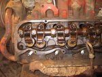
I am hoping my rocker stand looks as good internally as the rest of the head does. Pic attached.

5* of crank rotation! That is a good piece of information to have to illustrate just how small that sweet spot is. That is only 1.4%! I can see how it could be difficult to find.

Many other folks have gone through this same thing and not found that sweet spot, I just keep after 'em to keep trying, you will find it! 50psi is outstanding!

But...if the rocker stand itself is totally plugged where it's "foot" meets the cylinder head port, then no oil will ever emerge from the rocker assembly. In that case, remove the rocker assembly and set aside, then keep rotating slowly until oil floods from the feed orifice.

I have been cleaning some totally blocked feed rocker stands the last few days when I can stand up. The oil sludge has turned to hard carbon and must be picked out, then followed up with a carbide burr inna die grinder, then miniature wire brushes! These parts are irreplaceable, we have to save all we can that can be reconditioned!
 

Attachments

  • IMG_0931.jpg
    IMG_0931.jpg
    99.5 KB · Views: 1,829
I am hoping my rocker stand looks as good internally as the rest of the head does. Pic attached.

5* of crank rotation! That is a good piece of information to have to illustrate just how small that sweet spot is. That is only 1.4%! I can see how it could be difficult to find.

Your assembly does look decent, just typical oil varnish and no sludge visible!

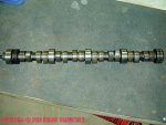
Here's a pic of a typical camshaft for a sv. Look closely at the #2 and #4 cam bearing journals. You can see that the oil holes are not drilled at 180* to the camshaft axis, but rather are "offset" and drilled across in one-third of the journal. So that provides an "intermittent/timed" oil squirt when rotating the crank/camshaft by hand, that hole is a nominal 3/16".

Of course, when the engine is running, that provides a controlled flow of oil in a steady stream to your eyeballz and oil pressure gauge, the volume is "regulated" by the timing/location of those oil ports in the cam journals and the location of the corresponding ports in the cam bearings and block drillings coming off the oil galleries. Thus the oil pressure is consistent, with volume controlled by that "timing" deal!!

I'm currently doing another engine, I'll try and get some much better shots of all this stuff and use those to finish off that "old iron" document! That motor build is covered in this thread:

http://www.forums.IHPartsAmerica.com/gas-engine-tech/1144-ultimate-IH-fourbanger.html

And the engine I'm using for that core is possibly the worst one I've ever seen internally as far as having all the typical sludge/cam bearing/oil pressure issues, when I originally started dealing with that motor about 5 years ago, I was still "discovering" schnizz about this whole valve train lubrication issue. And if ya think the inside is nastee, wait until ya see the shots of the water jacket!!!
 

Attachments

  • DSCN0005.jpg
    DSCN0005.jpg
    108.9 KB · Views: 1,765
Following your instructions I was able to get the motor turning freely and I was able to verify great oil flow to the valve train. :cornut: thank you for taking the time to create the old iron doc as well as answering my questions. It is greatly appreciated.


- Mike


your assembly does look decent, just typical oil varnish and no sludge visible!

Here's a pic of a typical camshaft for a sv. Look closely at the #2 and #4 cam bearing journals. You can see that the oil holes are not drilled at 180* to the camshaft axis, but rather are "offset" and drilled across in one-third of the journal. So that provides an "intermittent/timed" oil squirt when rotating the crank/camshaft by hand, that hole is a nominal 3/16".
 
Great!!!

Keep us in the loop regarding how the engine sounds/performs once ya git 'er runnin' on her own!
 
The bolts should be snugged up in a "cris-cross" pattern, bringing the rocker stands slowly into contact with the head surface. I do this without the pushrods in place. I have a home-brew tool that I then use to lever the rocker arm against the valve spring, and engage each pushrod in turn.

I can't quite understand how you are snugging down the assembly without the pushrods in place. Well, actually, I can understand that part, its the "how the heck do you get the pushrods in there afterwards?" that I have a problem with. Are you compressing the springs far enough to move the rocker arm out of the way to allow the pushrod to be installed? What does this maybenite tool you made look like?
 
This process is real ez man!

This allows ya to just install the rocker shaft(s) with no effort and align the rockers with the valve tips perfectly and really "feel" the mounting bolts when ya snug 'em up.

Then, go back and slide each pushrod into position verifying that each is seated in it's respective lifter pocket (with assembly lube on the ball tip of course).

The tool I "discovered" for doing this is a actually a 16" long pin spanner used in working with chrysler drop-out style third members from the musclecar era, used to set the pre-load on the carrier bearings which are adjustable.

I "hook" one pin on top of the rocker and use the tool to lever the rocker open against the valve spring pressure, just far enough to allow me to use the other hand to engage the pushrod tip with the rocker arm ball (or pocket if a boat rocker), then release it!

The tool works great even both Scout II and pickalls adjacent to the brake booster if so equipped.

So use your imagination and figgr how to homebrew something similar. I made another one out of a actuator lever for a plumbing ball valve, but it's too short and doesn't provide sufficient leverage to use it single-handed!

****************

I just went out to the shop to take some pics of the tool. It's now part of a kit I use for dealing with any engine lubrication diagnosis or service. Guess what...I loaned the kit to monte last month and we've not used it yet! It's at his place about 100 miles from here!

I'll ask monte to take a pic of the tool and post it in this thread!
 
How hard should the 9/16 plug be to get in place. I tried this last week and messed up 4 plugs just to get two in. After I installed the shaft back on the head. I used a oil pump primer with the valve cover off and they both leaked bad. When I put the plugs in they took a lot more than just tap tap tap to get them started in. After they were in about a half inch they would just slide in to place. Where am I going wrong, or would a plug that is .540" be better. It is aprox. .025" smaller than a 9/16 plug.
 
how hard should the 9/16 plug be to get in place. I tried this last week and messed up 4 plugs just to get two in. After I installed the shaft back on the head. I used a oil pump primer with the valve cover off and they both leaked bad. When I put the plugs in they took a lot more than just tap tap tap to get them started in. After they were in about a half inch they would just slide in to place. Where am I going wrong, or would a plug that is .540" be better. It is aprox. .025" smaller than a 9/16 plug.

First off...verify that the plugs you are using are the dorman 555-092 p/n. Look inside the cup on each one and make sure you can see the number stamp. Many times when I grab a handful of these out of the bin at the supplier's, they are badly mixed up! That is why nowadays I only buy 'em from the wholesaler in sealed boxes of 10. I have scruud up a number of these installs myself in the past!

Yes...the initial opening in the end of the rocker shaft is "oversize" when ya stick the cup in place for seating. That aids in properly aligning the cup as it enters the seating area.

The punch used to install must snuggly fit the upset in the new plug, otherwise the plug will distort when knocked in place.

I stand the shaft on end on a solid surface (the floor) in order to seat the cups, ya can't do this chasin' the shaft around layin' on the bench!

Yes, the plug is somewhat hard to knock into the hole. It needs to be, otherwise it will either leak or actually blow out. They are a relatively soft steel so that as they are installed in an interference manner, they will create the needed seal.

There is a learning curve to doing this, especially since they items are small and much more difficult to install than a typical soft cup plug in an engine block.

Also...on one occasion...I serviced a pair of rockers shafts that I'm certain were actually an aftermarket-supply part. At one time the shafts were available that were non-oem parts. Both of those shafts did not have the "counterbore" in the end to allow the cup plugs to align when installed, I wasted a whole dam box of plugs trying to knock in four good ones! In that case I also finally measured the holes and found 'em to be undersize as compared to the oem shafts. So I ended up starting over using a box of metric cup plugs that measured out to have a proper interference fit when finally seated. Those two shafts ate my lunch and required two trips to the supplier to come up with the correct schnizz. So now I always check the shafts for I.d. Size once the old plugs are removed!
 
Thanks. Do you know what the I.d. Of the stock shafts is. Because mine didnt seem to be counter bored. Maybe I might have after market one(s). The inside of them looked damn clean to be 32 years old. The plugs I used werent dorman. They are sep thats all I have access to. They came out of a new pack and are stamped 9/16 on the inside of the cup.
 
I just got the 80 runnin on all 4 and I have alot of noise still. Pulled the valve cover and found that I have 2 lifters not pumping up all the way. Will a marvel oil with new oil and filter help clean out the lifters?

I also noticed that not all the rockers are dribbling, it seems to be the intake valves. Whats the best way to clean the oil passages in the rockers? Havent taken the rocker assembly off yet to check condition of rocker shaft. I have 60psi cold, 40psi hot at idle and good oiling at the rockers. (threw it all over the hood and me.)

any opinions?
 
I just got the 80 runnin on all 4 and I have alot of noise still. Pulled the valve cover and found that I have 2 lifters not pumping up all the way. Will a marvel oil with new oil and filter help clean out the lifters?

I also noticed that not all the rockers are dribbling, it seems to be the intake valves. Whats the best way to clean the oil passages in the rockers? Havent taken the rocker assembly off yet to check condition of rocker shaft. I have 60psi cold, 40psi hot at idle and good oiling at the rockers. (threw it all over the hood and me.)

any opinions?

If you don't have solid oil drool at each rocker arm and down onto both the pushrod tips and the valve tips, then ya really don't have a rocker assembly that is oiling properly! Instructions for douchin' the rocker assembly is right here in this thread, starting at post #19.

The oil pressure numbers are encouraging....and if...you do have oil drool at "some" of the rockers, then the #4 cam bearing is functional.

The only way to handle lifters that are non-func is to remove 'em (keep in exact order as removed, never mix lifters on cam lobes!), disassemble each in turn (one at a time) and clean 'em back to a sterile format! They will be just as nasty inside as the rocker shafts...there is no way any kind of stuff in the oil can get inside the lifter, clean all the gunk out, and then transport it somewhere else (into the sump). I use carb cleaner and acetone for cleaning all the tiny lifter components, along with much patience.

You need to positively identify which lifter/rocker assembly is making noise, do that by pressing down on the suspect rocker/pushrod hard while the engine is running. If you can "feel" the tap increase in intensity and hear an increase in noise, that is the one that is non-func, there will be more than one, this is a typical engine that has set for an extended period and this is to be expected.
 
So I need to pull the lifters that have an issue and clean them? Is there any parts inside that should be changed or do they just get replaced?
 
so I need to pull the lifters that have an issue and clean them? Is there any parts inside that should be changed or do they just get replaced?

I'm dropping the ball all over the place man, sorry!

No, there are no parts inside any lifter that are replaceable.

Let me make that a bit more clear...any particular lifter was set up at the point-of-manufacture with "selective fit" guts. And after many thousands of miles of operation, each one is worn in to it's respective internal components and camshaft lobe. So we never want to swap internal parts around, nor, swap a lifter away from it's original installed position. This is a basic tenet of engine work, even when working with so-called "solid" lifters that are used with an adjustable valve train.

Also...on the oem side, ihc used over the years at least two vendors for lifters for all I-4 and sv applications, those are identified very well in the service manuals which have extensive information regarding dealing with hydraulic lifters in general. Using that information you can see how each lifter was I.d.'d originally, though they are interchangeable form one engine app to another as a set, the individual components which make up each lifter do not interchange.

On occasion I carefully disassemble and clean each lifter if it's base appears to be ok to re-use on the cam lobe it's mated to. This is not something normally done in routine engine service as no one will pay for having that kind of work done when it's far cheaper to just replace 'em.

But when you see what the inside of these items look like, you will soon understand how tedious they are and really appreciate how such a precision part can withstand total lack of regular oil change intervals and being allowed to remain stationary for so long! If the actual lifter base is ok, then a careful cleaning will bring 'em to life for a long period of time if oil is changed on a regular basis.

Some folks advise never using a new lifter on an in-service camshaft. But I have no problem with that if the lifters show only normal wear and the cam lobes show no wear at all. I simply treat 'em with assembly lube and stick in the hole, then run the motor for "break-in" as if both cam and lifters were replaced as a set. I've done that quite often over the years on my own stuff, I'm running one right now that has about 20k miles on it (392).
 
Well hopefully I will be pulling the rocker assembly off tomorrow and I have purchased a kd hydraulic lifter removal tool. I saw reference to one in the IH manual that I have. I have already made a lifter/pushrod index so as to not mix up anything and get them back into the wrong hole. I want to do as little tear-down as possible to this engine right now. If I can get everything to oil correctly I will run it while rebuilding a replacement that I'm getting ready to pickup next week.
 
I use the "lifter popper" tool onna as-need basis. They can be a real bitch to pull if heavily varnished in place.

Sometimes they come right out with only a magnet probe.

On the problem children, I pull the lifter up as far as I can get it. Then rig a long plastic tube on a can of carb spray and blow it all around the lifter where it exits the bore. Then use your tool to work it up and down with more carb spray and something like a penetrating oil that is solvent base (kroil). Takes alotta patience but they will finally come out.

The trickledown of using that procedure is ya will end up removing the pan to get all the crap that broke loose in the process out of the sump. That allows ya to blow solvent down the lifter galleries and chamber and get some of the loose mung out.

Some of the worst looking valve trains due to heavy crusting and varnish have yielded the easiest lifter pulls. The cleanest ones are the most difficult...go figgr!
 
Pulled it apart today and everything looks pretty good. I have some wear on the rockershaft but not anything that would be considered abnormal, no ridges, cuts or scoring. Same with the rockers themselves.

There is a few questions though, there are 3 stantions that are oiling stantions? Does that present a problem? I also checked the stansions for length and they all match within .002 on there mount surface. My book says nothing about it, are these figures acceptable?

I have taken the rocker assembly all apart inspected, cleaned, and made sure that all the oiling passages are clear and working. It was not very dirty to start with, but I have noticed that the po was into black rtv and it seems to be everywhere. The lifters came right out without issue and turning the engine over by hand and looking into it, the cam appears to be in good condition with no flat lobes, scoring, or imperfections.....at least that I can see without taking the engine apart. I will be doing the disassembly and cleaning of the lifters this week after work. The pushrods are in good shape on the ball and socket and are not bent.

More to come.
 
Back
Top