I-4 and SV Engine Non-Oiling Rocker Assembly

Using a suitable drift, knock the fresh plug into position. It should be driven in so that trailing edge of the cup is just past that first rocker stand hole...no deeper. If ya don't drive it deep enough, then the hold down bolt won't go through the hole.

Repeat this process for the other end.

That tool I use is perfect for seating these plugs, it'sa push rod from a '62 corvair flat sixbanger!
 

Attachments

  • Rocker Shaft Plug Install2.jpg
    Rocker Shaft Plug Install2.jpg
    30.3 KB · Views: 3,089
Now let's reassemble the rocker shaft.

Here we see the correct orientation of the rocker stands for the nine stand assembly. The set of stands I've selected here is a mix of the three different part numbers, so you can see that the foot of each stand which mates with the head has a slightly different shape. There are two points here that are critical...

1) the third position from the left hand end must have the "oiler" stand installed in correct orientation!

2) the third position from the right hand end must have a stand installed that has the "cutaway" foot, so that it will not interfere with the cylinder head bolt head.

The type of stand installed in the other seven positions is not critical as long as they are clean!
 

Attachments

  • Rocker Re-assembly1.jpg
    Rocker Re-assembly1.jpg
    46.6 KB · Views: 3,134
Here I've turned the critical stands upside down so ya can see the shape of the foot.. Notice that the oil hole on #3 from the left has been cleaned out.

The spacers are also seen in their approximate position. And the oil spit hole for each rocker bushing May be seen in it' proper orientation which is up.
 

Attachments

  • Rocker Reassembly2.jpg
    Rocker Reassembly2.jpg
    44.9 KB · Views: 3,128
One last point to verify so we don't have to tear this apart and redo it later.

The shaft itself must be oriented with the end that has the two stand holes closest together to the left. This shaft is not symmetrical and May not be swapped end for end, nor can it be turned upside down!
 

Attachments

  • Rocker Reassembly3.jpg
    Rocker Reassembly3.jpg
    54 KB · Views: 3,083
Ya gotta clean and inspect each rocker arm for the following:

...condition of the ball end which engages the push rod socket.

...condition of the pad end which engages the valve tip.

...cleanliness of the lube holes at both the inserted rocker tips.

...condition/size of the bronze rocker bushing insert.

Those tiny spit holes at each tip of the rocker must be sterile! Very important. If they cannot drip oil onto the push rod socket or the valve tip, extreme, rapid wear will occur at those points. As the wear increases, the lifter can no longer compensate for varying valve assembly geometry and lifter noise will begin and continue, it will not go away due to this wear!

Once the engine is running, you must observe oil drool from all of those rocker tip interfaces, it it does not drool, then ya gotta correct that!
 

Attachments

  • Rocker Oil Ports.jpg
    Rocker Oil Ports.jpg
    38.3 KB · Views: 3,096
Here's what I use for engine and rotating assembly lubrication upon re-installation. Same product is used for "cam lube".

This stuff goes on bearing journals and inserts, any thrust surface, etc.

For actual hard surface contact points such as push rod tips, rocker tips, etc. I normally use a moly-fill grease such as used for wheel bearings, not the old fashioned fibrous stuff, but the more modern stuff marketed for disc brake hub bearings.
 

Attachments

  • Assembly Lube.jpg
    Assembly Lube.jpg
    41.3 KB · Views: 3,072
And here is the completely re-assembled rocker shaft. The oem nylon insert bolts and the thick, hardened washers are in place in each rocker stand.

Once again, verify that the third rocker stand from the left is the oiler stand...and the third rocker stand from the right is the "cutaway foot" stand.

All that is left is to put a dab of sealant on the tip of each bolt before lowering the assembly against the head. I use either hylomar (preferred) or permatex #2 as the sealant, that must be done for the four bolts which penetrate the intake ports in the head. If ya don't do that, ya will have vacuum leaks and oil smoke. Go ahead and seal all the threads, it won't hurt anything. Do not allow sealant to get anywhere near the oiler hole though!!!

When the bolts are tightened the final time, use no more than 12ft.lbs. Of torque or you will crush the stands or crack 'em, resulting in oil bypass. The nylon inserts and sealant will keep the bolts in place just fine, that is why they are there!
 

Attachments

  • Rocker Assembly Complete.jpg
    Rocker Assembly Complete.jpg
    57.7 KB · Views: 3,092
Now let's look at some of the crap that the po and hiz/her "mechanic" will do to scruu up these thangs!

Ya gotta look real close at this pic. Someone has used a belt sander on the bottom of each rocker stand to remove material! But instead of trying to make 'em all the same "height", each one is different and most were ground off at an angle to the shaft center line!

The one on the left is the worst, ya can see daylight under the straightedge. Think what this does to the rocker shaft when tightened down! And this one had two rocker stands cracked through the mounting bolt holes so oil would just run out the stand and not "load" the hollow shaft.

In the case of the assembly this shot was taken from, the oiler stand was way short...so all the oil was spillin' out the bottom, none was reaching the rockers themselves or the rocker tips!
 

Attachments

  • Cut down rocker stands.jpg
    Cut down rocker stands.jpg
    71.4 KB · Views: 3,106
Part of this same botchinated rocker assembly...someone had punched out the valve tips (they are a press fit and then staked), and put washers under each one to extend the tip! Idea was to "pre-load" the hydraulic lifter to make the rattle go away!

But they used a different thickness washer under each tip! And all the stands were ground off a different amount and none of 'em were "square"!

This is very similar to what tren and Chad long found when they cranked that fresh-built 266 that was "squeaking" when they cranked it the first time.

All of this crap is what resulted when someone tried to "fix" lifter knock, in fact...the sonjamotor I took these parts from had three sets of new lifters installed to "fix" the noise. The lifter rattle came and went over time (nearly 10,000 miles!!!) as the cam bearings gradually disintegrated, this did not happen within a very short time period of operation.

The cam in this engine was not "flat", and all measures out to spec and will either be re-used...or turned in for a re-grind core...owner's choice.
 

Attachments

  • Shimmed rocker tips.jpg
    Shimmed rocker tips.jpg
    134.4 KB · Views: 3,054
Last edited:
We still have more information to add to this thread, especially regarding rocker arm assembly "variations" and ways to mix and match components if need be.

But here's a link that describes a tool I just finished for driving the oil pump either for use in diagnosing rocker assembly lubrication issues or cam bearing failure:

http://www.forums.IHPartsAmerica.com/tool-talk/1032-oil-pump-drive-system.html

Just a more advanced method of using the basic "cut down screw driver" oil pump drive tool.
 
Last edited:
Obviously I've overlooked an update to this thread regarding the "boat"-design rocker arms and their companion rocker shafts, so I'll be posting that soon.
 
Let's look at a "boat design" rocker assembly that is mounted to the cylinder head using only five stands and bolts. The springs seen take up the space where formerly the extra four rocker stands were positioned. And this rocker shaft is considerably different in design and execution than the nine stand/welded rocker shaft.

Difference one...this shaft is drilled through for only five mounting bolts.

Difference two...this shaft has no witness marks serving as assembly aids when mounting to the head. This shaft must be mounted so that the oil orifices for the rocker arm contact are down towards the head, otherwise, rocker oiling will be significantly reduced resulting in rapid wear and most likely valves sticking from lack of sufficient lubrication.

Difference three...the boat-design (or "stamped") rockers bear directly on the shaft at only two distinct wear points. Otherwise they are a sloppy fit on the shaft and only held in alignment by the spacers and springs.

All other inspection points apply to this type assembly as well, including removing the end plugs and swabbing out the internals of the shaft. Once that is done and the shaft wear points are measured and suitability for re-use is determined, then new core plugs must be correctly installed in each end.

This shaft was just recently removed from an sv engine by forum member ss2 and his pop, ihgramps. The motor has been parted out. However, this rocker assembly shows that some attention has been paid to oil changes over the years and the actually light varnishing tells me the motor was never significantly overheated. All parts on both of these assemblies are re-useable...so the roth boyz have a rocker assembly credit here at binder university! Much nicer parts than I see on the average!
 

Attachments

  • Baot Design Rocker Assembly.jpg
    Baot Design Rocker Assembly.jpg
    128.7 KB · Views: 2,633
Here's a close up of the rear end of the rocker shaft on the passenger side bank. The second stand from the left is now the oiler stand. In actuality, it's in the same position as the third stand from the left onna nine stand assembly...but, the spring has taken the place of the stand that was eliminated due to cost considerations.

You can easily see that there is no bushing in this rocker...in fact, the rocker is forced into contact with the shaft at the load points by the pressure exerted by the push rod/lifter/cam lobe combo and by rocker tip contact with the respective valve stem. Otherwise it's a real sloppy fit on the shaft and is free to "rock" side-to-side due to high rpm "harmonics" that might be present when the motor is over-revved (not a normal condition due to the asthmatic condition of the typical IH sv engine!).
 

Attachments

  • Boat Design Rocker Assembly 2.jpg
    Boat Design Rocker Assembly 2.jpg
    126.5 KB · Views: 2,686
Here is one pair of rockers (intake and exhaust) that are removed to show the wear points. And the shaft shows the same condition.

Notice the oil groove formed in the rocker when it was stamped originally. That channel aligns with the oil hole in the shaft if the shaft is assembled with oil holes down! The wear points are on either side of the channel.

There is really no effective way to measure the rocker wear in the shop except by visual inspection, there is no "hole to check for roundness or "spec". Also the rocker tip should be inspected for wear at the valve stem interface, and same for the pocket in which the push rod seats. There is an oiler hole in the push rod pocket that must be clear of varnish build-up or sludge so that the push rod tip May lube. The push rods themselves do not carry oil as is found on some chryfordrolet motors.

Use a micrometer or caliper to measure for "roundness/wear" of the shaft bearing surface at each pair of rockers locations.

In this pic, the rocker shaft is upside down so that the wear points May be seen! Do not re-install to the cylinder head like this! Please!!!
 

Attachments

  • Boat Design Rocker Assembly 3.jpg
    Boat Design Rocker Assembly 3.jpg
    117.4 KB · Views: 2,626
I read the entire rocker discussion and did not see the setup that is on my 1975 - 304 Scout that we just bought . It has nine stands and bolts and boat type rockers . The whole top end is very clean and looks like it was recently gone thru by a p.o . He also said it was " ticking" when he last ran it "a couple years ago" . I pulled the covers . We started the engine carefully and ran it for a few minutes. Looks ok except for this . Turns out the engine had been sitting for an unknown amount of time with 2 stuck intakes and 2 correspondingly bent push rods . I know this is a common issue . The problem is finding 2 of these push rods . They are ball/ball , approximately 8.9'' long , closed end (and I am beginning to think May not be stock) . None of my usual sources list these pushrods . The rockers/shafts /holes/stands are clean and were on their oil holes correctly . The formerly stuck valves are now free (at least for the moment) . The rocker shafts pressurize correctly. Any thoughts on this situation would be appreciated and if you have any of these pr's consider them sold.
 
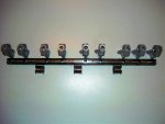
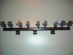
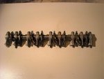
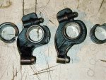
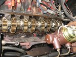
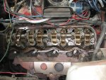
Nine stand rocker assembly with boat rockers, someone's been diddlin' in the sand box before you!

Classic case, there is no telling how these rocker systems May have been butched by the po virus in the past. I've even seen motors that had a mix of boat and welded rockers on the same shaft! No freakin' way that pos can oil!!!!

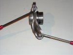
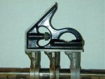
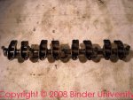
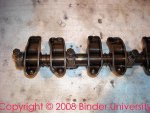
If it's a true nine stand rocker shaft (not a re-drilled five stand), it should have been flipped upside down so that boat rockers can oil.

We have reconditioned/inspected ball/ball pushrods for 152/266/304 on the shelf here at ihon (we refer to those as the "short" ones!). You won't see those in the online store, you need to call Jeff and order. If he's out-of-stock at his location, he'll call me and I'll drop-ship. I'm looking at a box of about 35 pieces right now!

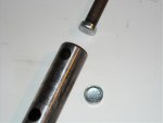
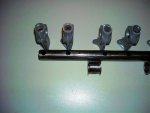
There are two designs of the boat rocker ball/ball pushrods, depends upon who the vendor to IH was at the time. One type has a distinct "ball" on one end, the other end is a somewhat radiused tip. The other style has two "radiused" tips. Guess I need to update this thread with examples of all four designs, (two long styles and two short styles).

T's certainly possible that someone May have had customs made at some point or simply boneyarded wrong stuff! These oem pushrods do not oil through the center of the tube, the balls have no oil orifice like some other oem motors use. But oil ports would not hurt anything as long as the ball radius is correct along with the length.

When we run out of these reconditioned pushrods, we'll have a batch of new ones made by our manufacturer (not the same source as the oem stuff), that's not an issue though a significant quantity must be ordered all at the same time.

Let's see...you are now the fifth individual I've discussed this same thing (stuck valves due to non-lubrication) with since last Saturday! One was a 152, two are 304, the other two are 345. Only one of the motors had correct parts all the way through (the early 152), and it's issue was simply the rocker shaft was completely plugged closed throughout by sludge.
 
Last edited:
Hmmm.... My truck has boat rockers and 9 stand shafts.

It currently has 13,300 miles on it, had 10,000 when I bought it in January 2007. I am the second owner and I was told by the original owner, by the fire chief, that no engine work was accomplished on the truck except for tune ups & oil changes, etc.
It is a v-392e / ic & tq carb with a casting date of July 1974, and the truck was built January 1975. The engine serial number on the LST agrees with the serial number stamped in the block.
Engine s/n 1353965

photos attached.
 

Attachments

  • Copy of Left cylinder head.jpg
    Copy of Left cylinder head.jpg
    96.6 KB · Views: 1,010
  • Copy of Right cylinder head.jpg
    Copy of Right cylinder head.jpg
    92.9 KB · Views: 920
Back
Top