I-4 and SV Engine Non-Oiling Rocker Assembly

thanks to all for the info...have ordered 4 from Jeff at ihono . Hope to have the Scout running soon .

Great!

I sorted another set of sixteen ball/ball short pushrods today and worked through several more rotten rocker assemblies to see what I can yard out as far as parts go. Looks like I have one more set of sixteen that will be usable, along with some singles. So those will go south the next time I send a shipment down.

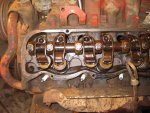
Deep in the pile of rocker assemblies I found another nine stand/boat set. This one has obviously been "recycled" and used at one point with welded rockers, then flopped over and used with boat rockers. And...there is one five stand boat assembly that had one welded rocker on it! The welded rocker is dam near welded to the rocker shaft from lack of oil!
 
yes the 9 stand shafts with boat style rockers is an oe set up, used in 74-75 model years.

Oh....my mistake. After reading all the engine & valve train threads, I was under the impression that the boat style rockers & nine stand rocker shafts were not a stock configuration.

I took some photos when I was replacing the valve cover gaskets last year. Looked at them this week and wondered if something was amiss or ????
I did run the engine with the covers off to verify oil flow & it was good on both sides. All four drains were clear also.

Thanks for the confirmation that it is a correct configuration.
 
Turns out the engine had been sitting for an unknown amount of time with 2 stuck intakes and 2 correspondingly bent push rods .

I am going to suggest that you completely drain the old putrid fuel and refill with fresh. The old gas will stick intake valves quicker than lick-I-deesplit. I always see the intake valves sticking under your conditions sitting/stinky old gas and bent pushrods.

Now like mm stated non oilers will cause sticking valves also but........ As a precaution the fuel should be changed out. Even residual varnished fuel system internals can pollute the new fuel enough to cause issues and that is why I add a very slight amount of yamaha racing 2 cycle out to the first bit of new gas.
 
Thank you Robert . I am also going to spray a little bit of carb cleaner thru the still sticky intake spring . Hopefully this will drip down the valve stem and start working any varnish/crud off the valve . I will also spray some oil towards the guide before re-start. When manually depressed and then released, #2 intake slowly (2 seconds) returns to the closed position . I am hoping what looks like a recent valve job was done correctly and that the guide is not too tight . All of the valve springs have an internal 2nd dampner spring. Is this a common setup ? I would also be interested in the success rate you guys have had using compressed air thru the plug hole to hold valves closed in order to change a cracked valve retainer on a different valve that I just noticed . I have special tools for this type of job for vw's and porsches that we use in my business but have never tried this on an American engine. Thanks again for your time .
 
An air hold works just fine on the engines for replacing valve springs, no different than any other ohv motor.

Do not spray/drool any lubricant on the valve stem to "free " it as it will mask what I am convinced is a non-lubricating rocker assembly. I lightly "tap" or bounce on the valve tip with a soft-face hammer, and lets the spring finally seat the valve after the "shock" applied. The re-assemble and run it, if you use your current rocker assembly that was installed when this happened, you can watch it happen again within 15>20 minutes of operation and it's obvious the rocker system that has the stuck valve is not oiling!

I fully understand Robert's experience with valves "stuck" by varnish, but I've never experienced that anomaly regarding one of these engines, the problem is always lack of rocker lubrication for one or more rocker/valve sets.
 
Ok, let's assume a under lubed stem. The rocker arm shaft and holes are clean and the boat rockers were covered with oil when the valve covers came off. The shaft has zero gall marks ,no wear ridges and the rockers are nice and loose. Motor had been sitting for years. I cranked it over with no coil wire until it had oil pressure for a minute . The pan was clean of debris. When the replacement pr's get here my "plan" is to lube the valve(so that it won't hang open, dropping the pr) and watch for the correct drip onto the valve . Remember, using a crowbar I can open the valve , crowbar off - it now takes maybe a half second to close. Way too long . But , one in 5 times it will correctly snap shut instantly. As per your instructions I did brass hammer it . So... I'm planning to run it slowly, watch for proper oiling and blindly hope the valve loosens up. I will compare drip rates valve/valve. Worst case I guess the heads come off ? What do you think ? Your thoughts are appreciated .
 
Thank you for the update! Between your project and towpainter's, we got two successful oilers so far this week here at ihon!
 
Ok so I read this thread after being sent the link for it as I was asking about the rocker shaft assemblies. I am good with every thing so far. I've been rebuilding a 345. I am now reassembling the motor and I'm ready to bolt the rockers back on. I have been reading through the repair manual step by step to make sure I don't miss anything. Well it clearly states about the nylon pellet bolts and such. Once learning what this was. I went and cleaned and inspected the bolts to make sure. And I do not have these self locking pellet type bolts. I know from evidence found the motor has been rebuilt before. So not sure if it never had them or po replaced them with common hardware, which the book says do not do.

So my question is how import are these bolts? And where can I get them?
Btw. Thanks to this thread I learned that the end caps could be removed to clean the shafts which I have now gone back and done. Mine weren't very dirty but can't hurt right.
 
Hello? Any one? I'm stressing about these bolts. Are they needed. And if so where do I get them? Want to finish my motor.
 
It is not imperative to use those bolts with the nylon pellets. You do need to use either the oem washers or use replacement thick grade 8 (hardened) washers between the bolt heads and the soft aluminum rocker stands.

Any replacement 5/16-18 x 3-1/4 grade 5 bolt will work. I have a box of 50+ on my bench now, all clean/used ones. Do not go any longer than 3-1/4" in length or you risk a bolt bottoming in a blind hole that was not tapped deep enough at the factory, the proper length is 3-1/4".

You must use something like hylomar or permatex #2 on the threads of the bolts which penetrate the cylinder head ports, otherwise oil will be pulled into the combustion chambers and four cylinders will smoke...and you will have four vacuum leaks as well.

The bolts should be snugged up in a "cris-cross" pattern, bringing the rocker stands slowly into contact with the head surface. I do this without the pushrods in place. I have a home-brew tool that I then use to lever the rocker arm against the valve spring, and engage each pushrod in turn.

Once all the bolts are snugged, then tighten each with a 8" ratchet, if you use standard torque for that size bolt, you May crack the aluminum rocker stand. If you use a torque wrench for doing this, then set it for no more than 12ft./lbs.
 
Do you use the nylon pellet bolts? If so where do you get the new nylon from? How much for some bolts? The washers apear to be oem. But bolts are just standard hardware. They are correct length @ 3 1/4" from bottom of head to tip of threads.
With a 1/8" thick washer. I have 5 stands per head so need 10 total. Thanks
 
On page 3 after you complete the first round of running the oil pump it states you rotate the engine backwards 10 rotations.

Just curious, what is the purpose of rotating it backwards vs forwards?


in order to try and keep all resources regarding the topic of this thread in one place, I'll re-post a document I've prepped (it's in draft form and has not had the jpegs embedded) regarding how to treat these motors that have been sitting non-rotated for several months/years.

The whole idea here is to prevent wiping out the cam bearings during initial dry-start rotation of the crank/cam shafts. Much of the time, the cam bearings in these engines are not damaged going in, but will quickly fail if a proper pre-lube procedure is not performed. All it takes is about three rotations of a "dry" cam that has "stuck" to the babbit layer of the cam bearing to wipe 'em out. From that point on, it's all down hill, no way to go back and "fix" anything except for replacing the cam bearings with new!
 
do you use the nylon pellet bolts? If so where do you get the new nylon from? How much for some bolts? The washers apear to be oem. But bolts are just standard hardware. They are correct length @ 3 1/4" from bottom of head to tip of threads.
With a 1/8" thick washer. I have 5 stands per head so need 10 total. Thanks

We don't have any new bolts with the nylon pellet. The ones we do have are reclaimed from engines that we part out and recondition the usable parts.

As for cost of used ones, contact Jeff at IH Parts America/530-268-0864. If he doesn't have a set of 10 nice ones at his location, I will dropship from my location. I should have a full set that actually have the IH logo on the head, but not all of 'em over the years had that designation. These were originally black oxide finish.

Do I personally use the "pellet" bolts? Sometimes, if I have a full set. But I'm not anal about that, I normally do not re-use much of the hardware on these engines other than the stuff that is somewhat special. Your motor will never know it doesn't have "pellet" bolts holding it's rocker stands down, but it will know if ya don't seal 'em!
 
Last edited by a moderator:
on page 3 after you complete the first round of running the oil pump it states you rotate the engine backwards 10 rotations.

Just curious, what is the purpose of rotating it backwards vs forwards?

Good question! No one has ever asked about that "10 turns backwards"!!

The reason...I'm anal about this stuff since we've seen so many engines destroyed by cranking over with the cam journals "stuck" to the cam bearing surfaces. I want to create a lubricating oil "wedge" between the journal and the bearing, just like the oil wedge that forms when the crankshaft is rotating at speed. That is standard practice when dealing with "friction"-type bearings such as the cam bearings in these engines. A "friction bearing" is one that has no rolling elements incorporated in it's design.

Since at that point we've run the oil pump for an extended period and hopefully fully flooded the rods/mains/lifters/cam bearings/rocker shaft assembly, we wanna spread the oil wedge across all the flat bearing surfaces so that when we do fire the motor off, it will be fully lubed as well as possible. Not as good as doing "assembly lube" when we build the motor, but next best thing!

By rotating backwards, we are spreading the oil wedge all around the bearing/journal circumference (I hope!) in the opposite direction from the direction the wedge forms when the engine is running, we're simply doing the best we can without pulling the main and rod caps to slime the journal/bearing interface, same for the cam journal/bearings.

The 10 rotations is just a judgment thing to make you think what is occurring and not rush to fire the motor in your excitement after determining that it is oiling and does have oil pressure!!

Thanks for bringing this up, it reminds me that I need to go back into that document and complete it with the embedded pics!
 
Well that makes good sense. I appreciate the answer.

Also, I am in the process of following the document. I am up to the point of the the 10 backwards rotations. I also do not have oil on the valve train yet. But I do have 50 psi. I am hoping it shows up after the rotations.

I will take your advice not not dispair just quite yet...

Thanks again.


By rotating backwards, we are spreading the oil wedge all around the bearing/journal circumference (I hope!) in the opposite direction from the direction the wedge forms when the engine is running, we're simply doing the best we can without pulling the main and rod caps to slime the journal/bearing interface, same for the cam journal/bearings.

The 10 rotations is just a judgment thing to make you think what is occurring and not rush to fire the motor in your excitement after determining that it is oiling and does have oil pressure!!

Thanks for bringing this up, it reminds me that I need to go back into that document and complete it with the embedded pics!
 
well that makes good sense. I appreciate the answer.

Also, I am in the process of following the document. I am up to the point of the the 10 backwards rotations. I also do not have oil on the valve train yet. But I do have 50 psi. I am hoping it shows up after the rotations.

I will take your advice not not dispair just quite yet...

Thanks again.

Keep in mind...the oil holes in the cam journal/cam bearing only line up and allow oil flow up to the rocker feed stand/shaft through about 5* of crank rotation, so finding that sweet spot takes much patience! Go sloooooow!

Many other folks have gone through this same thing and not found that sweet spot, I just keep after 'em to keep trying, you will find it! 50psi is outstanding!

But...if the rocker stand itself is totally plugged where it's "foot" meets the cylinder head port, then no oil will ever emerge from the rocker assembly. In that case, remove the rocker assembly and set aside, then keep rotating slowly until oil floods from the feed orifice.

I have been cleaning some totally blocked feed rocker stands the last few days when I can stand up. The oil sludge has turned to hard carbon and must be picked out, then followed up with a carbide burr inna die grinder, then miniature wire brushes! These parts are irreplaceable, we have to save all we can that can be reconditioned!
 
I am hoping my rocker stand looks as good internally as the rest of the head does. Pic attached.

5* of crank rotation! That is a good piece of information to have to illustrate just how small that sweet spot is. That is only 1.4%! I can see how it could be difficult to find.

Many other folks have gone through this same thing and not found that sweet spot, I just keep after 'em to keep trying, you will find it! 50psi is outstanding!

But...if the rocker stand itself is totally plugged where it's "foot" meets the cylinder head port, then no oil will ever emerge from the rocker assembly. In that case, remove the rocker assembly and set aside, then keep rotating slowly until oil floods from the feed orifice.

I have been cleaning some totally blocked feed rocker stands the last few days when I can stand up. The oil sludge has turned to hard carbon and must be picked out, then followed up with a carbide burr inna die grinder, then miniature wire brushes! These parts are irreplaceable, we have to save all we can that can be reconditioned!
 

Attachments

  • IMG_0931.jpg
    IMG_0931.jpg
    99.5 KB · Views: 1,712
I am hoping my rocker stand looks as good internally as the rest of the head does. Pic attached.

5* of crank rotation! That is a good piece of information to have to illustrate just how small that sweet spot is. That is only 1.4%! I can see how it could be difficult to find.

Your assembly does look decent, just typical oil varnish and no sludge visible!

Here's a pic of a typical camshaft for a sv. Look closely at the #2 and #4 cam bearing journals. You can see that the oil holes are not drilled at 180* to the camshaft axis, but rather are "offset" and drilled across in one-third of the journal. So that provides an "intermittent/timed" oil squirt when rotating the crank/camshaft by hand, that hole is a nominal 3/16".

Of course, when the engine is running, that provides a controlled flow of oil in a steady stream to your eyeballz and oil pressure gauge, the volume is "regulated" by the timing/location of those oil ports in the cam journals and the location of the corresponding ports in the cam bearings and block drillings coming off the oil galleries. Thus the oil pressure is consistent, with volume controlled by that "timing" deal!!

I'm currently doing another engine, I'll try and get some much better shots of all this stuff and use those to finish off that "old iron" document! That motor build is covered in this thread:

http://www.forums.IHPartsAmerica.com/gas-engine-tech/1144-ultimate-IH-fourbanger.html

And the engine I'm using for that core is possibly the worst one I've ever seen internally as far as having all the typical sludge/cam bearing/oil pressure issues, when I originally started dealing with that motor about 5 years ago, I was still "discovering" schnizz about this whole valve train lubrication issue. And if ya think the inside is nastee, wait until ya see the shots of the water jacket!!!
 

Attachments

  • DSCN0005.jpg
    DSCN0005.jpg
    108.9 KB · Views: 1,665
Following your instructions I was able to get the motor turning freely and I was able to verify great oil flow to the valve train. :cornut: thank you for taking the time to create the old iron doc as well as answering my questions. It is greatly appreciated.


- Mike


your assembly does look decent, just typical oil varnish and no sludge visible!

Here's a pic of a typical camshaft for a sv. Look closely at the #2 and #4 cam bearing journals. You can see that the oil holes are not drilled at 180* to the camshaft axis, but rather are "offset" and drilled across in one-third of the journal. So that provides an "intermittent/timed" oil squirt when rotating the crank/camshaft by hand, that hole is a nominal 3/16".
 
Back
Top