350 Buck Truck Project engine revival

c9e77125.jpg


Going through the box of fel pro #260-1075 gasket set and trying to make heads or tails out of some of the small parts. :confused5:

I can't find the oil pump mounting leg gasket

I can't figure out the 8 5/16"copper washers

any tips on what is necessary for the 304 engine.

The oil pump was done with a melling rebuild kit by my engine guy so that accounts for some of the extra gaskets.


Also I was advised that I should get busy on those intake ports on the heads but they seem very good. Since the heads have been assembled I did not see how that was going to happen easily without getting grind dust everywhere on the freshly assembled valve parts.


Last edited:
Those gasket kits contain parts for all variations of the sv motor and the four cylinder stuff to an extent. Fel-pro has revised all the IH gasket sets since last fall and they are now making their way into the parts chain. That's called "consolidation". That set probably had the lifter cover gaskets for both the 266/304 (narrow gasket), and the 345/392 (wide gasket). But it had only head gaskets for a 304 and only intake gaskets for 266/304. The gasket set for 345 or 392 would be virtually identical, but have only head gaskets and intake gaskets for the correct application (and ya gotta make sure if dealing with a 392, you get a gasket set for either ic or non-ic motor).

That gasket for the rear cam plate on the block is for the four cylinder application only! The copper washers are used in some peripheral accessories on engine equipped with an air compressor for air brakes. The larger copper washer is for the drain plug on some pans.

There are at least three different types of oil filter adapters used over the years, pick the gasket that matches your adapter and has the proper number of mounting holes.

The oil pump leg gasket is plainly visible in your pic, that is the one with the holes in each end with a larger hole in the center.

The large "ring" fiber gasket is for the bolt-on oil filter canister, you don't use that either on your app.

The brown fiber gasket in the lower left corner is for a fitting on some valley covers for connecting either a road draft tube (early engines) or a pcv "adapter". It's also used on four banger lifter chamber covers.

I see two fuel pump boss gaskets, one thicker than the other, use that one behind your fuel pump.

There are variations in design and thickness of course regarding the oil pump body gaskets. Some oil pumps used a cover plate only for determining end clearance with an assortment of shim gaskets, some pumps use a ground flat wear plate to set the end clearance with a different pattern gasket.

Personally, I see no advantage in doing anything to those fresh heads other than bolting on! Any port work that will result in possibly a performance gain is going to have to be extensive on these heads!!!! And it's done on bare heads, not units that are assembled.
 
Last edited:
Thanks for the reply. It clears up a few things. The only gasket I see for the oil pump is for the oil pump outlet but the mounting leg one is missing. I re-attached your pdf from the oil pump shimming thread just for reference for other folks doing a 304.

Your words again from that thread regarding the 2 oil pump gaskets

"ok, here's a .pdf'd scan of the two gaskets.

Using the lexmark all-in-one printer setup, if you set the scaling to "none", it appears that it will print the templates actual size. I've verified that on my end...so now I've learnt shit too! The problems I had in the past making template scans were involving various older hp printer/scanners.

But since you are a pooter dude, ya prolly know all about that schnizz!

To review...ya need to always use both gaskets, even though one goes under the secondary mounting leg to shim the pump off the block and carries no liquid. Otherwise, there is a very real danger of either cracking the pump housing (since it's cast iron) or distorting the housing when torqued so that the pump gears could potentially bind.

I'd dare say that the majority of these engines in service that ever had a oil pump r&r'd, most likely do not have the gaskets in place! Or even worse...sum dumscruu used rtv!"
 

Attachments

  • Oil Pump Mount Gaskets.PDF
    209.8 KB · Views: 424
Heads are on the engine. I have not torqued them on yet because the head bolt washers are looking a bit tired. I think I should replace them with fresh grade 8 washers unless there is something special about the hardness of the original head bolt washers.
 
heads are on the engine. I have not torqued them on yet because the head bolt washers are looking a bit tired. I think I should replace them with fresh grade 8 washers unless there is something special about the hardness of the original head bolt washers.

The oem washers are quite hard 45-50 rcs and thinner than an average g8... They are fine to use again.. Apply a moly anti sieze/thread lubricant to the threads, under the bolt head, and between the washer and the head.

Also make sure you chase all head bolt holes with a tap to make sure nothing will impede the bolt clamping properly.. Than torque to the hi end of the recommended torque 95-100 ft/lb in 3 stages 30, 60- then finish at 95-100. Use general cross wise pattern from the center out.
 
Sorry, I misunderstood about the "dead leg" shim/gasket for the oil pump! Make one! Use a piece of one of the gaskets that you are not going to use as long as the paper is correct thickness.

Robert is right on regarding those washers, they are "specials" and are commonly used on many other engines, they can be found through the arp stuff, but your machine shop guy prolly has 'em in bulk stock also if needed, that's the kind of stuff engine machine shops keep that is sourced from specialty engine component suppliers, not a common auto parts.
 
Thanks for all the help. There are many slight details and procedures that keep coming up that are not explicit in the manual or stored in my brain but are common knowledge to you guys with tons of engine building experience.

I hope to finish the heads tonight and get that front timing cover on. Anything noteworthy on attaching the front cover. I already pressed that front seal on. I assume that timing cover gasket goes on dry and the bolts get a little anti seize rather than a sealant. Also I should not torque them down without getting that dampener in place for perfect centering of the seal on that fresh speedi sleeve.

One thing I noticed is that the rear of the timing gear edges line up perfectly while there seems to be a tiny bit of overlap on that crank gear on the cam gear from the front.

Also looking ahead looks like my all my valvetrain parts are coming in this week. I got a new box of lifters and I was wondering the best way to prep the lifters for install. Should they be soaking in oil now?
 
Last edited:
thanks for all the help. There are many slight details and procedures that keep coming up that are not explicit in the manual or stored in my brain but are common knowledge to you guys with tons of engine building experience.


Anything noteworthy on attaching the front cover. I already pressed that front seal on. I assume that timing cover gasket goes on dry and the bolts get a little anti seize rather than a sealant. Also I should not torque them down without getting that dampener in place for perfect centering of the seal on that fresh speedi sleeve.

Nothing very note worthy really, but I am guilty of some type of sealant on gaskets because I don't like come backs.:icon_crying: hylomar or permatex 2 are either fine. I use moto seal because I like it and it is light gray instead of black.
For centering the cover on the crank nose I have an alignment tool but using the hub to aide in alignment is fine..

One thing I noticed is that the rear of the timing gear edges line up perfectly while there seems to be a tiny bit of overlap on that crank gear on the cam gear from the front.

If I recall one gear is a bit wider and a little overlap is normal.


Also looking ahead looks like my all my valve train parts are coming in this week. I got a new box of lifters and I was wondering the best way to prep the lifters for install. Should they be soaking in oil now?

There are differing opinion on lifter pre lubing but pumping them up is not necessary. Just oil the lifter bores, lobes and the lifter faces liberally with th cam assembly moly lube. And oil the push rod end along with the push rod seats.

The prelube regimen will do the rest. Expect a bit of ticking upon initial start up as the air in the lifters is run out.. It won't hurt anything.
 
I am beginning to see first hand how these projects can take years to complete. Life keeps getting in the way. Finally, we have decent shade tree mechanic weather again and I have been wrenching on the Scout cooling system.

Timing cover is on. The threads on the fuel pump were slightly chowed on the blind hole (as opposed to the through hole). I see how that happens too ...fuel pump bolt length on the blind hole. If too long it bottoms out and stresses the aluminum threads. My solution was to grind about an 1/8 inch off the bolt and use loctite it held for now but I know a few fuel pumps later that timing cover May need a thread insert. It was the right solution at the time as a helicoil kit for 3/8 coarse runs about $32 bucks at napa.

Oil pump is on and it was shimmed with a ,067 washer added to the .041 original washer. Missing dead leg gasket was fabbed up along with a matching gasket for mounting.

The oil pickup mounting stud on the main bearing cap bolt was of course torqued down on the wrong side. Correct location was on the passenger side of engine. I retorqued it the main cap bolts to 85 ft lbs and hopefully this did not disturb anything there.

Oil pan is going on next.

One thing I noticed was the valley pan bolt hole ears had been distorted by the po cranking down on the gasket so we got that straightened out on the drill press with a delrin rod and plastic block with a notch carved into it. Then just pressed it back into shape. This was all done cause before when you set the valley pan down with no gasket there were huge gaps created by the distorted bolt tabs. No way it was going to seal properly.

This weekend hopefully get that oil pan installed completely. Then assemble the valvetrain. Also fill with oil and prime engine to check oil pressure and top end oiling. If all goes well on with the valley pan too. So looks like I might be a few weeks out from getting it up and running.
 
The stripped fuel pump mount hole is real common!

Be sure to use some sort of sealant on the two 1/4" bolts at the rear of the pan that thread into the main bearing cap. Same stuff ya use on the flywheel/flex plate bolts and the intake manifold bolts. Those two holes enter directly into the chamber between the crank and the seal and oil will leak if ya don't seal the threads and lead ya to think the rear main seal is leaking!
 
Yeah those were the original fuel pump bolts and the bolt was hitting bottom on that blind hole. Must be some sort of design flaw.

I bought hylomar on ebay so I can be like Mike on those 2 oil pan screws and the flex plate bolts. You know that big hub back there for the flex plate mounting is still on the bench. Anything special bout mounting that big old hunk of flex plate spacer on the crank??
 
yeah those were the original fuel pump bolts and the bolt was hitting bottom on that blind hole. Must be some sort of design flaw.

I bought hylomar on ebay so I can be like Mike on those 2 oil pan screws and the flex plate bolts. You know that big hub back there for the flex plate mounting is still on the bench. Anything special bout mounting that big old hunk of flex plate spacer on the crank??

The flex plate spacer should have both faces spotlessly clean! Same for the flex plate and the retainer the bolts go through.

But...carefully inspect the area around the hub boss, that is prone to cracking and same for the four mount points for the torque converter.
 
Hey mr mayben I found the perfect service truck for you or Jeff.
1000 bucks obo craigslist las vegas
bigones1.jpg

1960 metro mite

I wonder if it would fit on a Scout II chasis??
 
hey mr mayben I found the perfect service truck for you or Jeff.
1000 bucks obo craigslist las vegas
bigones1.jpg

1960 metro mite

I wonder if it would fit on a Scout II chasis??

I can't believe ya found that listing!

I've actually seen that rig (without the hood ornament with the major attractions) parked beside a building in wickenburg for many years! It set there for at least three years I can remember, I used to take the wickenburg shortcut going back and forth to phoenix/tucson and all points beyond when I was gainfully employed!

A decent mite is extremely hard to find!
 

Attachments

  • metro 80 c.jpg
    metro 80 c.jpg
    33.6 KB · Views: 1,491
I had no idea that these rocker stands were going to be such a tight fit. It seems to be a factory 9 stand setup with boat rockers on this 75 truck.

I spent some time struggling with the reassembly of a rocker shaft this morning. New rocker shaft o.d. Is .862" which matches the good parts of the old shafts. I got 8 rocker stands on the shaft starting them by hand and then using a drill press as a press for a precise position. I made some delrin fixtures to protect the aluminum stands. The last stand was a bitch and I gave up before I broke something. This one seems to be out of round by as much as .010" maybe more.

Any tips on making the rocker shaft hole on the stand a better fit? What causes this out of round condition?

Also there were some mystery brass nuts that came back from the machine shop with the rocker stand bolts ( and all the rocker arm/shaft stuff)??? I am not sure where these came from but they are the same threads as the rocker stand bolts. I sure would like to know where those brass nuts go.

Arms are sore from wrestling rocker stands all morning as I managed to start assembling stuff wrong the first time.

This is all just a practice run for when I do the other engine in my Scout.
 
Probably only .0005 or less of an interference fit. You can safely hone out the tight stands with a brake cylinder hone and wd40. A few licks in a drill press will probably be enough. Only hone to allow a hand slip fit.

The out of round condition is from torquing

I don't know about the brass nuts as they do not go on your engine assembly. I have seen the pre assembled rocker assembly come with a couple of stand bolts and nuts installed to keep the thing together during shipping.
 
The rocker stands are aluminum...dead soft aluminum castings. They are easily "collapsed" (compressed) when installing if the bolts are over-tightened, that is why we do not use a "torque spec " on those and just feel for tension. The feel of the tension is also masked by the nylon pellet inserted in the bolt along with the application of some sort of thread sealant before installing.

Every rocker stand I recondition gets "honed" using a ball hone (flex-type). That cleans 'em up just enough so that they are slip-fit onto the rocker shaft. Once they are sterile, I then carefully inspect the bores for size and the top of the stand for cracks/distortion, if any damage is noted, they get tossed in the scrap metal buckets, on average, probably one in five are no good when inspected.

Brass nutz??? You been hangin' out with monte, dboy, and mikee roth from IHSTO at the rallye??? They musta slipped ya the brass nutz, they do that shit all the time to fook with folks, the nutz they think they got are brass...but in actuality they are plastic.

There ain't no brass nuts in them motors and no nutz of any kind used anywhere near the rocker assemblies! When I recondition/assemble/ship rocker assemblies, I thread a throw-away nut on each rocker stand bolt to keep 'em in place while in transit, then the nuts are removed/discarded before installing the rocker assembly.

When I tear down these rotten rocker assemblies for reclaiming the parts, they can be a major bitch to get apart due to the collapsed rocker stand and the heavy varnish build-up.

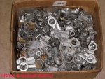
Need rocker stands??? This a a box of about 50 that have been semi-cleaned and graded for quality, but not completed for shipping. These are all in the ihon inventory. I have maybe another 100 or so that have not been processed at all but are for future salable inventory. There are four different variations of stands in that box all mixed up.
 

Attachments

  • Rocker Stands 002.jpg
    Rocker Stands 002.jpg
    78.2 KB · Views: 1,465
Last edited:
Brass nuts ... Definitely a good joke to play on someone to leave them head scratching for a while.

Also I tell you what it was like jamming square pegs in round holes with those overtorqued stands.

I May be calling Jeff about those stands if I find any belt sanded suckers or something along those lines.
 
Last edited:
Ok I need at least one replacement oiling stand # 151181-r1. For some unknown reason, there are 2 extra oiling stands placed equally apart on each bank.

c71dc00b.jpg

bab28a61.jpg

007f3288.jpg


I should replace all of them with a matched used set that mm has inspected but this budget is going way over at this point. Depends on the price for a full set. .... wish I could deal with another $200 hit but not an appealing option at the moment.
 
Last edited:
I talked erik into letting me have a go at his 75 parts Scout. So I think we have a replacement. Looked like the valve covers had never been off. 2 things notable: another 9 stand boat setup and some grey goo oil dripped out of the borrowed rocker shaft via the oil stand.
b35bdf0c.jpg


Mmmm fresh manifolds

speaking of manifolds I recently heard that if you can locate a boneyard combine with a 345 in it you can use those manifolds to run the exhaust straight up through the hood. Too bad I can only dream about stuff like that on my daily driver in kalifornia.
 
Last edited:
ok I need at least one replacement oiling stand # 151181-r1. For some unknown reason, there are 2 extra oiling stands placed equally apart on each bank.


I should replace all of them with a matched used set that mm has inspected but this budget is going way over at this point. Depends on the price for a full set. .... wish I could deal with another $200 hit but not an appealing option at the moment.[/quote ]

I got maybe 20 rocker stands just like that cracked one ! dam guud thang ya inspected closely ! but the cracking is not the only "failure" mode !

there are many variations of the mix and match of the rocker stands over time . and at least three different part numbers May be found on the raised casting number .

the oiler stands can be found that have oil "holes" or..."oil slots" .

then there are stands that look like oiler stands from the top (they have the cut-away mounting foot for cylinder head bolt-head clearance in some positions), but have no oil hole .

then, there are stands that have no oil hole and no cut-away mounting foot, those can be used in only a few positions, otherwise the mounting foot will hit the head of the head bolt when installed .

because the entire rocker assembly is totally interchangeable passenger side-to-driver side, it must be assembled so that the correct oiler stand is mounted in the correct position to cover the oil supply hole on either cylinder head...otherwise no oil to the rocker shaft ! you could use an oiler stand in every position on the shaft if ya wanted (or need) to, but that would be a waste of oiler stands ! that way there is no possibility of head bolt interference when mounting .

the gray grunge ya found in the sludge in the donor rocker is most likely a mixture of oil, moisture, and cam bearing metallic sluff-off, typical failure mode of this old non-maintained shit.

 
304home.jpg


Crawling along here. Last week I rented a 4x7 uhaul and brought the 304 home from our machine shop without incident. Tonight I just installed the lifters and micheal's 304 ball ball pushrods using a lever I fabbed out of a big aluminum bar because I already installed the rocker shafts prior to bringing the 304. I also did the valley pan tonight.

I have a question on which is the best technique to drop the intake manifold on. I will be using a cherry picker to place the manifold.

The question is: will the intake gaskets stay in place ok with a healthy dose of the copper seal spray? Or is it better to stick the gaskets to the intake instead of the heads?

I am assuming that the gaskets will be stuck to the heads good enough and that if I drop the manifold very slowly the gaskets will stay put. The valve covers are still off the heads. Also I am a gonna get all new grade 8 bolts with hylomar on the threads even though I seem to have all the copper clad intake bolts. Same with the exhaust manifolds although I intend to use anti seize on those threads.
 
Your engine looks very nice by the way.

The gaskets will try to move around, especially down..

Here is what I do.

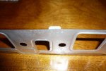
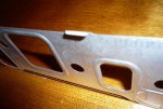
Before applying the copper spray, I line the gaskets up exactly with the ports and bolt holes then I bend the little tabs on the upper edge of the embossed shim gaskets at a sharp 90* toward the head so they hang on the top edge of the head in perfect alignment. They stay in exact alignment during lowering the manifold. After assembly you can straighten them so the valve cover gaskets can line up on them ans stay fast also.

The copper bolts were intended for the exhaust manifolds to aid in fending off corrosion.
For the manifold the g8's are a good ider and I like to use a g8 hard washer under each head also.

Picture for reference is a 304/152 manifold gasket

9889d1274029064-350-buck-truck-project-engine-revival-p1010367-large-.jpg

9890d1274029064-350-buck-truck-project-engine-revival-p1010366-large-.jpg
 

Attachments

  • P1010367 (Large).jpg
    P1010367 (Large).jpg
    52.1 KB · Views: 1,459
  • P1010366 (Large).jpg
    P1010366 (Large).jpg
    56.2 KB · Views: 1,365
Last edited:
I can well understand the sitch steve due to your need to use that work platform from the wheelchair!

I'd install the intake before dropping the engine in! And even I use the cherry picker for doing that since I'm not supposed to lift more than 25lbs. And that intake weighs about 53lbs. I use one of the cheepee engine lift "plates" that bolt to the intake manifold flange to hang the manifold from.

Or...have erik do the intake install heavy work, he's better than a cherry picker!

Robert's described technique is the same as what I do.
 
Back
Top