Engine Cpt Vacuum Users and Emissions

scoutpappa

Member
Any aftermarket air cleaner system either has a "boss" on the base plate for installing a fresh air hose, or can be drilled and have a fitting installed.

A workaround "breather" element added to an engine originally equipped with a flame arrestor turns it into an open pcv system. Sure that can be done, it's simply not "legal" if that matters to anyone (and in many locales throughout the u.s. It does!)

but never attach an aftermarket breather to the flame arrestor component! The boss on the valve cover is a simple 3/8" npt thread, install a correct transition nipple to the valve cover.

Neither can you simply remove the valve cover and drill a hole in it for a fitting. On valve covers that are manufactured with a provision for a flame arrestor or a pcv (many ihc-produced variations of these engines were produced with the pcv installed in the valve cover rather than the valley cover), there is a full length "baffle" spot-welded inside to reduce the chances of liquid oil escape back through the flame arrestor under certain engine operation conditions.

If you install an open element "breather" on the valve cover position, you will find that it gets "dirty" very quickly and in most cases will become soaked with engine oil. That means it needs to be cleaned and you will probably see that the cleaning needs to be done really often!

When adding a closed pcv fitting to an air cleaner base, the location is critical. If it's exposed to extreme fluctuations of air flow across the carburetor air horn, it will not operate and actually becomes a secondary pcv that sucks oil vapor/blowby right into the carb venturi.

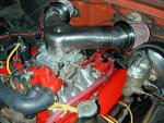
The blingy air cleaner adapter shown on this engine of mine was a nightmare to attempt to use a closed pcv. I plumbed it many different ways and it just won't work. I eventually had to give up and revert to an "open" pcv and have to clean the open element breather every 5,000 miles or so. The hose in the pic is connected to a specialized fitting that is an accessory for that intake plenum and incorporates a contoured rubber grommet for sealing after a hole is drilled in the air horn. The mounting shown in this pic is a massive fail.

The only "filtered" air is the air that passes through some sort of actual filtration media, otherwise the air is dirty. Whether air goes through a carburetor or is drawn through the pcv system, it must be clean!


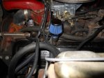
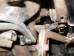
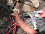
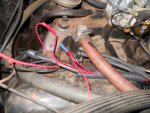
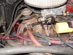
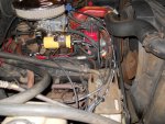
I am bringing this over to a new thread so I don't appear rude. From what I can gather on tx dot there really are no emissions tests or oem equipment I need. It appears 84' and older are exempt. But, I would like to have the systems that benefit the running of the vehicle (as a dd) so here are some pics of my engine compartment

attachment.php


attachment.php


attachment.php


attachment.php


attachment.php


attachment.php


attachment.php


attachment.php


attachment.php


So here come the questions

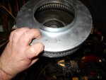
the flame arrestor is wrong?
I can use the ko in the air breather (or should use) to pipe in the arrestor?
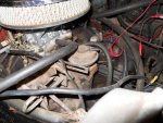
Can I leave the egr valve capped off or do I need to plumb it somewhere?
I have the little vacuum trees capped off, should I remove them completely and if so what size plug should I use?
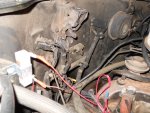
Wth is that little thing on the firewall that has vacuum lines that used to go to it?
This was a CA vehicle but the smog pump and most of the "emissions" parts are gone, what should I replace to make this truck reliabe?
If I don't need any of this what size plugs do I need to remove the al rails that are tapped into the exhause manifold? Those things make doing anything by the spark plugs a pita

this is basically how my Scout in high school looked minus the al rails and the vacuum trees. No flame arrestor plumbing, no egr valve plumbing, just two vacuums for the carb and one over to the booster. How much of this do I need, or the better question, how much of this should I eliminate? I know some of this May be "illegal" but hell the carb is "illegal", even the new one that is coming. The whole ignition is probably "illegal" so if I'm an outlaw shouldn't I go all out?:icon_evil:
 

Attachments

  • DSCN1943.jpg
    DSCN1943.jpg
    62.8 KB · Views: 1,514
  • DSCN1944.jpg
    DSCN1944.jpg
    85.1 KB · Views: 1,462
  • DSCN1945.jpg
    DSCN1945.jpg
    41.8 KB · Views: 1,376
  • DSCN1946.jpg
    DSCN1946.jpg
    59 KB · Views: 1,431
  • DSCN1947.jpg
    DSCN1947.jpg
    73 KB · Views: 1,408
  • DSCN1948.jpg
    DSCN1948.jpg
    89 KB · Views: 1,437
  • DSCN1949.jpg
    DSCN1949.jpg
    86.6 KB · Views: 1,456
  • DSCN1950.jpg
    DSCN1950.jpg
    82.9 KB · Views: 1,389
  • DSCN1951.jpg
    DSCN1951.jpg
    43.5 KB · Views: 1,399
The pcv system is an essential part of the overall engine scheme. Any internal combustion engine must be vented in some manner.

Prior to the mandated inclusion of pcv for the u.s. Market, we used a "road draft" system. That was a simple large volume tube that led to the crankcase in some manner and also had a form of baffle to prevent liquid oil from blowing out.

By model year '62, all ihc production had some form of pcv system as the road draft system was no longer "legal" for either 49 state or kalifornikate. This has nothing to do actually with the enhanced emissions regulations you face in the harris county market. The enhanced (read smog check) process is only mandatory in a few markets in texas (dallas county and surrounds, bexar county and surrounds, el paso, etc.) but someday will be state-wide no doubt unless the state of texas does finally secede from the union ....again. Enhanced emissions testing came into being in the spring of 1990 in texas, I was part of that "launch" since I was marketing and doing training for allen testproducts, the leader in emissions testing and engine analyzer equipment at the time.

The first pcv systems I'm aware of were used in inboard marine applications beginning in 1952 or so. And that was because of coast guard-developed regulations in regards to fire prevention in enclosed marine applications. Same for the use of "flame arrestors" on carburetors instead of a simple air filter (that is not the same as the flame arrestor used in conjunction with a closed pcv system).

As a business, we must be very careful in what we advise or discuss around here in regards to the subject of "emissions". Any of the common upgrades and workarounds we might allude to are legal for off-highway use only. Very few of the upgrades carry any form of emissions component exemption (such as a carb number). If the customer or ihon member chooses to "optimize" any emissions device or system, then we do not encourage that except for off-highway use.

That said, it's not a good idea to retain a non-functional egr valve. That will eventually lead to a minor/major vacuum leak point.

And since your pic shows a conversion to an "open" pcv through the use of the cleanable breather element, you should delete the flame arrestor that it is attached to as that serves as a major restriction now to fresh air flow. The actual pcv valve is a "balanced" component developed and calibrated for each engine application when the entire system is oem. That is why you see at least 50+ versions of a pcv valve replacement hanging on the wall at the parts house, they are not "all the same" in any regards except to their overall purpose.

The electro/vacuum device on the bulkhead is a "decel" valve component of the emissions system. Since you have no active vacuum operation of any device on this system right now except for distributor vacuum, then nothing that is part of the emissions system is operational. The vacuum switches in the intake manifold are water temperature controlled, if removed you will loose coolant at that point. The thread form is a common 3/8" npt.

That carburetor has no provision for connecting a vent hose to the charcoal canister, so simply leave the hose dangling in the engine bay and also do not connect the vacuum hose to the carb or intake manifold. Leave the canister plumbed as is and the fuel system will "vent" on it's own even though it's not legal for on-street use.

All the advice I've suggested is for off-highway use only.
 
Last edited:
Mike, I appreciate the constraints you function under in administering all the advice you give on this forum, so from now forward lets presume that this is all for off road use. This vehicle did pass in boise id so even with the wrong carb application and as far as I can tell only a catylitc converter in the exhaust it made id standards. So as I understand it I can do the following

take the passenger side vacuum switch and plug it with a ss 3/8" npt plug. (I can get these at the jobsite all day long but a length would help tremendously.

I can delete the egr (I think I saw a delete plate on the site but will have to call, I have it capped currently per the picture)

I need to leave the driver side vacuum switch because that is where my carb vacuums are fed from (but now I need to ask, is this a good spot to get vacuum from if it is a temp switch? Do I even have vacuum when I start the vehicle?)

and last but not least where is the line for the charcoal canister? I didn't even know I have one:icon_confused:

the back switch on the fire wall is a take or leave it. No harm no foul as long as no vacuum enters or leaves it so do I need to cap it or can I leave it open to air?

Oh is there a barb fitting I can pick up so that I can delete the arrestor? Thread/size/length?

And plug thread/size/length to delete those damn rails from the exhaust manifold? I really really hate those things. I can never get my arms in. Even made getting the borgeson joints in a pita
 
Many vehicles that have been put into an "enhanced" state of performance tune will show emissions numbers for "two gas" well under any federal or kali specification. And at the point in time that most of these vehicles were under "emissions warranty", the idle only test was all that was used, the dyno tests and the extended "four gas/five gas" tests had not been legislated into effect.

But common sense regarding emissions numbers makes no sense to the fookin' feds or the smognazi asshats in kali (such as bar/carb/scaqmd/etc.). So we're stuck with that shit, no matter if we actually run these motors much "cleaner" than oem spec for that point in time!

Yes, ihon does offer an "egr delete" blockoff plate of very high quality (not the shitty sheetmetal plate some vendors push that will rot right through due to the erosive/corrosive effects of exhaust gas). And...not legal for on-highway use!

Any penetration in the intake manifold is going to be a npt thread form (pipe thread). Actual sizes May vary with application, but a complete assortment of internal wrenching, brass plugs in 1/8", 1'4", 3/8" and 1/2" will serve you well. These are simple common plumbing items from the hardware store!

The npt thread for the valve cover boss is 3/8". All it needs to be is a nipple of about 2" for convenience, black iron, galvanized, brass, it doesn't matter. Even a "close" fitting is more than suitable. Any npt thread form must be sealed with either teflon tape, pipe dope, or a combination of both.

Do not feed any vacuum through or from any temp-controlled vacuum switch mounted in the intake manifold!!! Those are switches (they turn off and on based upon calibration/specification), those are not junction points or vacuum manifolds.

For plugging the a.I.r. Ports in the cylinder heads, I use a simple cup-point set screw, 1/2" x 20 (1/2" in length) treated with anti-seize. Do a search and you will see this issue addressed in many other threads including some with pics.
 

Attachments

  • Set Screw kit.jpg
    Set Screw kit.jpg
    66.9 KB · Views: 1,025
All the additional vacuum lines are fed from either ported or manifold vacuum as the source on the carb throttle body. That is where it all begins! If the low temp and high temp switches are faulty, then vacuum won't be applied or blocked when needed (all that shit is part of the emissions scenario). To bypass all that stuff for testing, just run the ported vacuum source directly to the distributor can. That way the egr and other crap are disabled for testing.

So...disconnect and plug the nipples on the carb. Keep the short hose that connects to the choke pulloff in place, ya gotta have that one! Then run a single hose directly to the distributor. That is the basics of what is needed to operate. Then ya can add back in each circuit one at a time in order to troubleshoot for leaks or inop components.
__________________
it's pretty simple actually:

youtube - never gonna stand for this by teachenor clark


I will look through the bins at the shop today. I'm sure I have an array of swedgelok plugs. Use the good stuff if possible. Also I have been looking/searching for the appropriate vacuum routing for when I get the new carb tonight from Jeff. Since I have two lines going over to the temp switch I am pretty much jerking off. I will have the electric choke kit so in reality the only vacuum I will need is to the vacuum advance on the distributor. So can I just either plug off all the other vacuums or just pipe them to themselves on the carb? The above is the closest I have found and who'd a thought it the quote is from you.
 
Alright failure to launch. I got the carb today and decided to slap it on. I didn't realize that the kit contained the egr delete so at least I have that accomplished. Some things I noticed between the two carbs. The 500cfm has 4 vacuum ports whereas the new carb has two (one for the advance and one for the booster I am assuming. The new carb has a slightly more outward and forward linkage so that is what really got me. Went down the road and shifted through all the gears in 10 feet. So I will have to set the shift linkage for upshift and downshift and I guess while I'm at it I need to see if I can get a little more time between 2nd and 3rd with the mechanical linkage. Or is that even possible? Also while running it in there was a slight popping from the exhaust at idle. Kinda of a bub bubbubbub bub. I'm sure I will have to fine tune it so I'll research that before the weekend. The throttle response was excellent. Very noticable on revving. It took up/revved up almost instantaneously. So I need to figure out what is going on on the low end. There is 64 in sharpie on the bowl so I figure the jets are #64. Also the choke wouldn't open up. When I was running I put a meter on the choke tabs and had 2.5vdc. When I pulled the hot I had almost 14.8vdc. It was running for about 5 minutes and no noticable movement so I'm confused. I took a spare 12vdc hot acc/run from the back firewall that was suggested. I grounded the choke on the coil holder screw that I have the unilite grounded to. Checked that for ground and it is good. So what am I doing wrong here? Other than my obvious ignorence I am very happy with the purhase and the work Jeff put in to getting the carb set up and the choke installed and all the new parts. Very rare these days to buy something and have all the parts and pieces in the box ready to go. I'm sure it's not even possible to get a new carb, bolt it on and have the truck fire up and run well from the box. Goes to show that when you get parts from the right people you get great products and support.
 
Regarding the holley2300/list 7448 carb you are now going to be using...

The electric choke conversions uses an internal vacuum source (manifold vacuum) to operate the choke pulloff. The pulloff system (piston) is inside the choke housing. There is no other connection required for the choke as far as vacuum goes.

The "other" 2300 shown in your pics is the incorrect list 4412, has only one single 5/32" vacuum tap for an "accessory" along with the other 3/8" manifold vacuum port used for either pcv connection or possibly for connecting a vacuum brake booster. That is a manifold vacuum source and one more reason why a 4412 is not the right choice for any IH sv engine application.

Your new 2300 (list 7448) also will have a 3/8" manifold vacuum port. However, on the passenger side of the metering block above the idle mixture screw, you will see an additional 5/32" port, that one is a ported vacuum source. That means that at idle, there is no vacuum available at that location and as the throttle plate angle increases from idle position, then that port becomes active in a very linear fashion and increases in vacuum signal up to a point of stability. When throttle plate angle decreases, so does that vacuum signal. That port is where you will connect your distributor vacuum.

However...as far as carburetors go, that particular 2300 is kind of unique in regards to the ported vacuum signal. At curb idle (I recommend you set that to 600 rpm for a manual transmission and 700rpm ((in gear)) with an automatic), you will see a nominal 3"hg at that port instead of the more common 0"hg. This is not an issue however, as it takes a nominal 5>7"hg to actuate the vacuum advance on the distributor, so that at idle, the distributor vacuum advance is not active.

Your oem intake manifold already has a fitting at the rear of the plenum for the pcv connection, leave that where it is. You can use the 3/8" manifold vacuum port to connect to the brake booster just as it's shown in your pic.

This another reason to delete the egr (for off-highway use!). If you attempted to connect all the temp-controlled vacuum switches to the ported vacuum tap, then under certain engine temperature conditions, the egr would activate at idle, resulting in an extreme vacuum leak, super-shitty idle quality, and a massive dose of exhaust gas being dumped into the intake plenum right when we do not want it to!
 
While you were posting, so was I!

You are correct, any modification such as this requires a bit of tuning for each engine application. It's real close to plug and play considering it's a major change from the oem stuff. We put a lot of time and effort into setting these up so the novice could attempt this install.

Our original conversion kits included the egr blocker and some additional hardware. Then we discussed that some folks would not need that and in order to reduce the retail price we decided to delete some of the parts from the kit. So it looks like Jeff "over-rode" himself and decided to put all the goodies in the kit after all!

Yes, we write the main jet set size on the carb bowl when we do the conversions so we will have a reference point for tuning purposes. That jet set is not what came in the carb from Holley, again, we want this to be plug and play based upon our experience in doing this over and over.

The idle mixture screws should be set initially to three turns out from seated. That is only a starting point and final adjustment is made after the engine is fully up to temp (minimum of 15 minutes run time). Then the mixture screws are tweeked alternately while maintaining a curb idle speed of 700rpm in drive.

As for the choke not opening...I "think" that when Jeff (or Darren or michael) installed the choke cap, they did not get the circular "pigtail" of the bimetal spring engaged with the choke lever inside the cap/body. So the spring is opening, but if it's not engaged, it's not moving the choke plate. Simple fix, pull the choke cap off and you will see exactly what I describe, and you can carefully "engage the tang" and re-install the choke cap. Start with the choke cap installed dead in the middle of the tick marks. Then after the engine is fully cold, tweek the cap one Mark at a time to the "r" side and try it. 90% of the time, the best setting for the choke cap is two tick marks "Rich".

The starting drill with this system...push the pedal to the floor one time and then remove your foot while cranking. Do not push it again or you will flood the motor. Once it fires, if the choke is adjusted properly, the fast idle cam should provide about 1500rpm and then start dropping off to 1100, then 900, then curb idle. Choke operation is based upon time, not engine temperature at all. Choke should go full open withing 3.5>4 minutes of "turn on".

When you kill the engine, even for 15 minutes on the hottest day, the choke will reengage because the electronic heater element has cooled down a bit. So the hot restart drill is the same as the cold start!

Since this is going to be your wife's dd, work with her very carefully to learn the best starting drill. This setup is not efi like she was used to on your Ford where the computer drives the car with only some low-level input from the driver! I doubt your wife was born when the Scout II was a hot ticket new...so back then we had to learn to drive and not assume a passive role in operation, so be gentle. I've been married four times and I know how learning experiences like this can become tense very quickly! For years, my wife has driven pooter-injected throwaway vehicles, so she's had to learn a whole new way of starting her Travelall with an electric choke!
 
regarding the holley2300/list 7448 carb you are now going to be using...

The electric choke conversions uses an internal vacuum source (manifold vacuum) to operate the choke pulloff. The pulloff system (piston) is inside the choke housing. There is no other connection required for the choke as far as vacuum goes.

The "other" 2300 shown in your pics is the incorrect list 4412, has only one single 5/32" vacuum tap for an "accessory" along with the other 3/8" manifold vacuum port used for either pcv connection or possibly for connecting a vacuum brake booster. That is a manifold vacuum source and one more reason why a 4412 is not the right choice for any IH sv engine application.

Your new 2300 (list 7448) also will have a 3/8" manifold vacuum port. However, on the passenger side of the metering block above the idle mixture screw, you will see an additional 5/32" port, that one is a ported vacuum source. That means that at idle, there is no vacuum available at that location and as the throttle plate angle increases from idle position, then that port becomes active in a very linear fashion and increases in vacuum signal up to a point of stability. When throttle plate angle decreases, so does that vacuum signal. That port is where you will connect your distributor vacuum.

However...as far as carburetors go, that particular 2300 is kind of unique in regards to the ported vacuum signal. At curb idle (I recommend you set that to 600 rpm for a manual transmission and 700rpm ((in gear)) with an automatic), you will see a nominal 3"hg at that port instead of the more common 0"hg. This is not an issue however, as it takes a nominal 5>7"hg to actuate the vacuum advance on the distributor, so that at idle, the distributor vacuum advance is not active.

Your oem intake manifold already has a fitting at the rear of the plenum for the pcv connection, leave that where it is. You can use the 3/8" manifold vacuum port to connect to the brake booster just as it's shown in your pic.

This another reason to delete the egr (for off-highway use!). If you attempted to connect all the temp-controlled vacuum switches to the ported vacuum tap, then under certain engine temperature conditions, the egr would activate at idle, resulting in an extreme vacuum leak, super-shitty idle quality, and a massive dose of exhaust gas being dumped into the intake plenum right when we do not want it to!

I installed the plate and plugged the switches for the time being until I can get to the hardware store to get the assortment of plugs you suggested. But because of the shift situation I had to re-install the wrong carb till this weekend where I will have more time to get the linkages adjusted. My biggest things now are sucking it up and getting a vacuum guage and I saw a meter at autozone that reads rpms as well as the usuals for a multimeter so I need to get these and a timing light I'm sure. My one concern really is the slightly rough idle with the slight miss. I'm sure this is a slight adjustment but because Jeff built it and set it I'm wondering if maybe something else is going on. It revvs beautifully no miss at all through the upper rpms and llike I stated previously it was almost instantaneous. Really could tell it is the right application there. So my big things are to make sure the choke operates correctly and get the idle right (mixture wise) the linkage should be failrly easy . Mark everything with a grease pin and set them back with the new linkage and adjust till everything lines up again, but I get nervous with the carb settings. I guess I'll do the normal thing and start on the driver side and bring the mixture screw clockswise till she stutters and the turn clockwise till she evens out nicely, open her up and listen for the cureve then repeat on the passenger side but really what is correct? Is it two and a half turns out like I've alway heard? I really don't want to change the plugs till I get the manifold and exhaust plugs I need cause those rails drive me to drinking. Everything I read says check the plugs but outside of a drive and pull a plug what is a standard setting? I'm looking for a baseline. I know I have to get the engine to running temp but when the temp guage showed warm the new carb was still in full choke so from reading other threads I know I have to have that sorted out first cause I am on the bypass circuit. Another question is, is the drivers side set screw th low speed needle adjustment and the passenger side the high speed adjustment?
 
while you were posting, so was I!

You are correct, any modification such as this requires a bit of tuning for each engine application. It's real close to plug and play considering it's a major change from the oem stuff. We put a lot of time and effort into setting these up so the novice could attempt this install.

Our original conversion kits included the egr blocker and some additional hardware. Then we discussed that some folks would not need that and in order to reduce the retail price we decided to delete some of the parts from the kit. So it looks like Jeff "over-rode" himself and decided to put all the goodies in the kit after all!

Yes, we write the main jet set size on the carb bowl when we do the conversions so we will have a reference point for tuning purposes. That jet set is not what came in the carb from Holley, again, we want this to be plug and play based upon our experience in doing this over and over.

The idle mixture screws should be set initially to three turns out from seated. That is only a starting point and final adjustment is made after the engine is fully up to temp (minimum of 15 minutes run time). Then the mixture screws are tweeked alternately while maintaining a curb idle speed of 700rpm in drive.

As for the choke not opening...I "think" that when Jeff (or Darren or michael) installed the choke cap, they did not get the circular "pigtail" of the bimetal spring engaged with the choke lever inside the cap/body. So the spring is opening, but if it's not engaged, it's not moving the choke plate. Simple fix, pull the choke cap off and you will see exactly what I describe, and you can carefully "engage the tang" and re-install the choke cap. Start with the choke cap installed dead in the middle of the tick marks. Then after the engine is fully cold, tweek the cap one Mark at a time to the "r" side and try it. 90% of the time, the best setting for the choke cap is two tick marks "Rich".

The starting drill with this system...push the pedal to the floor one time and then remove your foot while cranking. Do not push it again or you will flood the motor. Once it fires, if the choke is adjusted properly, the fast idle cam should provide about 1500rpm and then start dropping off to 1100, then 900, then curb idle. Choke operation is based upon time, not engine temperature at all. Choke should go full open withing 3.5>4 minutes of "turn on".

When you kill the engine, even for 15 minutes on the hottest day, the choke will reengage because the electronic heater element has cooled down a bit. So the hot restart drill is the same as the cold start!

Since this is going to be your wife's dd, work with her very carefully to learn the best starting drill. This setup is not efi like she was used to on your Ford where the computer drives the car with only some low-level input from the driver! I doubt your wife was born when the Scout II was a hot ticket new...so back then we had to learn to drive and not assume a passive role in operation, so be gentle. I've been married four times and I know how learning experiences like this can become tense very quickly! For years, my wife has driven pooter-injected throwaway vehicles, so she's had to learn a whole new way of starting her Travelall with an electric choke!

Feeling better. I'm the kind of person that gets frustrated when I don't understand what is happening from the process perspective. I have overturned the choke on my other Scout so I know that you have to pull the cap and engage the little curly cue on the spring. I will check that when I start this process again this weekend. The meter seems to be a must now that I really need to dial this motor in. I didn't realize the choke is timedp, I guess I assumed a temp control since the plate is being heated and thermocouple control is relatively easy to set up but very good to know because I exceeded that time frame considerably. I will call Jeff tomorrow to thank him again for adding all the goodies. Really have to get good with these systems because my wife has decided that her next vehicle is a 60's model Travelall. Is there a correct sequence to go through to set the mixture screws (ie drivers side to passenger side)? Do I need to adjust rev the motor adjust rev then move on to the passenger side. I know you guys can "hear" the right setting but my ears aren't there yet.
 
More info to come as you work through this...

But...the idle mixture screws on each side of the metering body controls the idle mixture only for four cylinder "sets". Four runners feed one set of four cylinders, the other four runners feed the other set of four. That is what we call a "dual plane" intake manifold and the ihc stuff is a "medium-high rise" design comparable to the best designs from the performance aftermarket!

So you alternately tweek the screws for highest manifold vacuum reading and smoothest idle condition. And we're assuming that currently your ignition timing is set nicely since we've delt with all that previously.

As for the kickdown for the tranny...with the new carb, it should be a direct swap over from the oem carb stuff, again, that is why we set these up so that they will drop right in place. But in your case, since the other carb was installed, someone has probable botched that to an extent. I'll have to look at the linkage setup again more closely. In the meantime, here's a pic of one of mine for reference, even though this is a 4v Holley. The throttle arm is identical to your 2300.

It's no big deal to drill an additional hole in the throttle arm to correctly position the kickdown. Also, the kickdown must be adjusted so that the throttle cable and the kcikdown slide are as close to parallel as possible, the action must be linear and progressive so that with the carb at idle, the kickdown is all the way forward. When the carb is at wot based upon the throttle pedal position, then the kickdown slide must be all the way back.

I spent three hours today working on this exact same thing on a recently converted older Travelall we provided the transmission and conversion parts for. A very high-dollar operation for a beautiful roundbody! But the fabricator simply botched the throttle connection/conversion, therefore the lokar kickdown setup would not work. And the throttle would only open to 3/4 so the highly modded 392 didn't perform much better than the tired old 304!
 

Attachments

  • Beater Beer Can Manifold.jpg
    Beater Beer Can Manifold.jpg
    92.4 KB · Views: 1,018
Noticed this thread so I thought I would breifly post a few things in order to help get things hopefully squared away. I personally put that carb together. All I did was pop open the fuel bowl and changed the jets and then installed the electric choke conversion. I did notice that on this carb that the choke had a ever so slight sticking to it. I noticed that the linkage going to the choke plate was ever so slightly rubbing on the carb body. I made a very slight tweak to it and everything at that time seemed just fine with the choke setting mid way. No other adjustments were made to the carb(idle mixture and curb speed). If I screwed something up please let me know as I need to know so that it doesn't happen again. I will say that the one I did for a previous customer had no issue's what so ever. As for the quick upshifts extend the kick down rod some as that will help change your shift points.
 
noticed this thread so I thought I would breifly post a few things in order to help get things hopefully squared away. I personally put that carb together. All I did was pop open the fuel bowl and changed the jets and then installed the electric choke conversion. I did notice that on this carb that the choke had a ever so slight sticking to it. I noticed that the linkage going to the choke plate was ever so slightly rubbing on the carb body. I made a very slight tweak to it and everything at that time seemed just fine with the choke setting mid way. No other adjustments were made to the carb(idle mixture and curb speed). If I screwed something up please let me know as I need to know so that it doesn't happen again. I will say that the one I did for a previous customer had no issue's what so ever. As for the quick upshifts extend the kick down rod some as that will help change your shift points.

Jeff, I don't think anything is screwed up. I'm very much an amateur when it comes to fuel systems so I'm sure the fault is on my end. Also this truck had the wrong carb installed and half the emissions crap is missing or plumbed weird. The vacuum advance for the distributor was plumbed into the drivers side vacuum switch for example. I just bit off more than I could chew in trying the swapover after work instead of waiting until the weekend but you know how it is when you get a new part. Also I just opened the choke for the interim as really I didn't have the time and information available to do much more last night. As for the setup. Once I got gas in it it fired right up and idled just had a slight miss, but man you could tell the difference when you revved the motor, way better than the other carb and as smooth as can be. So now I just need some more tools to set rpm at idle and nut up and play with the mixture screws. What is probably a 5 minute set up for you will take me hours to do but the experience is necessary. The other thing is I have to ask the stupid questions because I have never seen a Scout with the emissions intact, and with this one I purchased the truck with the setup that way it was. I have to get to a point where things are right for this application but it's hard to determine when you start with butchered systems from the get go. I spend alot of time on these forums trying to get the answers I need but alot of times I can look at ten different threads for about the same issue and come up with ten different setups. So hopefully you guys can bear with my ignorence until I get a little more confident.
 
We fully understand this is a major learning experience, and you certainly aren't the first person we've worked through this stuff! Seems like we had the same thing going on regarding your initial efforts at dealing with the ignition system???

This is a perfect example of exactly why this forum exists, this is a customer service tool for us, if you are successful regarding your experiences in learning how to deal with this old iron, then that will rub off on many more potential customers! Win/win for everyone!

Since you have chosen to "optimize" the emissions system and all the vacuum-related gadgetry, from this point forward let's forget about all that crap, in light of the fact that this rig is going to be used for off-highway operation only! We're not going to use anything other than the pcv system which is a must for any engine (or a road draft system for pre-emissions motors). So everything that is related to the external emissions apparatus is going to be deep-sixed.

There are multiple variations of the throttle control and transmission kickdown linkage used across the board for the 727 on both the Scout II and the pickalls. We can make what you have work right now with a bit of finessing, but by far the easiest path to take when dealing with po-butchered stuff like that is to use one of the lokar universal cable kickdown systems. But a warning...do not be tempted to simply bypass or not connect the kickdown linkage, that will result in a transmission that does not operate properly and May also result in rapid failure of the transmission itself.

Last nite, I pulled a virtually new (10 years ago) list 7448 out of the carb dip to prepare it for a build-up. Picked it up in a parts trade I made Saturday nite, this one had been allowed to get wet in a storage unit where it was found so it has some corrosion issues I will correct. I will use this mixer to explain anything you need to know about how to make the complete installation, we'll correct all your known engine setup deficiencies, and then tune the entire package for best performance. I'll make a run to town later today and pick up an electric choke kit for it, I keep everything else on hand here all the time.
 
Last edited:
Thanks guys. I will also take some better pics of the areas I need help with. The above were basically shots of all the vacuum users. I will get some clearer pics of the linkage area and I will also stop and see if the local parts house has a vacuum guage. Might get the meter too. Gotta run it by the boss, cause with all the parts I have gotten in the last two weeks it looks like Christmas every day for me. And Mike, still appreciate you getting me past all the misinformation I was getting for the ignition issues.
 
Alright I have purchased a mityvac system and an actron meter that can read engine rpms as well as dwell and normal ac/dc ohms, etc. So now I should be able to do something right?
 
A mityvac will certainly serve your purpose right now, and is an excellent tool to use for many other jobs, you will get a lot of service out of it.

The actron tach/dell meter is the same one I buy for gifts and use here in my shop. I'm not sure how it will display the dwell on the unilite, but I know it won't be damaged. I "think" it will display just like a pertronix or prestolite will, but of course the dwell on the unilite is non-adjustable. I'm suggesting that at idle, the dwell on the unilite will be between 29* and 31* which is perfect. If you later install the mallory six box, dwell really doesn't matter at that point. Also, the tach portion of that instrument will work fine with either the unilite or the six series cd box if you hook it to the coil terminal as specified.

We all face the same "budget" deal...all the time! That is why we are always aware of the dollar signs, if our customers blow the budget with incorrect purchases, then they won't last long!
 
a mityvac will certainly serve your purpose right now, and is an excellent tool to use for many other jobs, you will get a lot of service out of it.

The actron tach/dell meter is the same one I buy for gifts and use here in my shop. I'm not sure how it will display the dwell on the unilite, but I know it won't be damaged. I "think" it will display just like a pertronix or prestolite will, but of course the dwell on the unilite is non-adjustable. I'm suggesting that at idle, the dwell on the unilite will be between 29* and 31* which is perfect. If you later install the mallory six box, dwell really doesn't matter at that point. Also, the tach portion of that instrument will work fine with either the unilite or the six series cd box if you hook it to the coil terminal as specified.

We all face the same "budget" deal...all the time! That is why we are always aware of the dollar signs, if our customers blow the budget with incorrect purchases, then they won't last long!

Cool, then I got the right tools. First an update. I guess last night I tried to reinvent the wheel. So I mounted the linkage and the throttle cable in the exact spot as the old one. Success there. Then I nutted up and turned in the mixture screws until the set (very gently). Come to find out the driver side was about a turn and a half and the passenger side was barely a half. So set the screws to two and a half out. Started her up and she purred like a kitten. So then I let her warm up and set the idle speed with my new meter. Got about 750 in park and about 700 in drive. All the time this thing is running great. Took her down the street and she performed considerably better than she ever has. Came back home and played with the choke as she was cooling off. No success there but want to try one more time when she is truley cold. Then adjusted the screws in to about one and a half turns out and with a good romp to full throttle had a little puff (very little) of black smoke so now I need to know what to do with the mityvac. The instructions say you can read all kinds of issues but most of them concern hooking to a manifold vacuum. Where do I plug the mityvac in? Which port can I use to start checking for issues? Specifically Rich/lean mixture. If I can dial in the carb I will get new plugs this weekend and then move on to the power timing. Haven't got a light yet but if I have the carb right and then power time it and then know how to use my new druck then I should be able to get her top notch. Oh yeah, Jeff see it was my inexperience, and Mike, my wife said she likes the new carb alot. It has made a huge difference.
 
Hang in there dude, yore gonna learn all kindsa new shit. Even better, put momma on the forum here and let's let her do here own wrenchin', chicks always are better "learners' (I taught school for 14 years!!).

That carb does not have a "manifold vacuum tap" unfortunately (though I can add one but not by long distance!)

so...simply install a step-down "tee" fitting in that hose going to your brake booster, that is the 3/8" vacuum nipple. Then place a proper cap on that port when you aren't hooked up. That would also be an excellent spot for installing a vacuum gauge in your instrumentation array on the dash.

That instruction book that comes with the mityvac is an excellent resource, I can't recommend it enough, I still use it myself to refresh myself when stuff kicks my butt daily!

You can adjust only the idle mixtures at this point. The vacuum gauge is of no use for determining proper jetting, that will involve "reading" the spark plug insulator color, another lesson! But for now, we know that the #64 jets are so dam close that you most likely will leave 'em in there, that is why we change 'em from what Holley put inside when assembled!

And the slight smoke May be because the choke is not fully opening. We need to verify that also since you initially mentioned an issue with that.

Again...this stuff takes patience to work through in a step-by-step manner. There is a reason we take it in a particular order, you will understand that once you have gone through the process.
 
hang in there dude, yore gonna learn all kindsa new shit. Even better, put momma on the forum here and let's let her do here own wrenchin', chicks always are better "learners' (I taught school for 14 years!!).

That carb does not have a "manifold vacuum tap" unfortunately (though I can add one but not by long distance!)

so...simply install a step-down "tee" fitting in that hose going to your brake booster, that is the 3/8" vacuum nipple. Then place a proper cap on that port when you aren't hooked up. That would also be an excellent spot for installing a vacuum gauge in your instrumentation array on the dash.

That instruction book that comes with the mityvac is an excellent resource, I can't recommend it enough, I still use it myself to refresh myself when stuff kicks my butt daily!

You can adjust only the idle mixtures at this point. The vacuum gauge is of no use for determining proper jetting, that will involve "reading" the spark plug insulator color, another lesson! But for now, we know that the #64 jets are so dam close that you most likely will leave 'em in there, that is why we change 'em from what Holley put inside when assembled!

And the slight smoke May be because the choke is not fully opening. We need to verify that also since you initially mentioned an issue with that.

Again...this stuff takes patience to work through in a step-by-step manner. There is a reason we take it in a particular order, you will understand that once you have gone through the process.

Feeling alot better about this whole thing. I'm going to try to say this out in sequence so that it makes sense.

The truck starts well and idles great now.
There is no smoke (maybe a puff) when it starts ( that is normal for these motors from what I have read).

No smoke at all now until I rev her all the way up.

Then it is literally a puff.

One little puff of black smoke. And I mean a miniscule puff...almost nothing. But I am observing for any sign.

The truck shifts where it used to. I will take Jeff's advice and lengthen the rod and play with where it shifts. Second to third I would like to see a little more speed between shifts but this is not critical. There really is no dogging down of the motor where it shifts currently. All shifts are smooth. I did replace the cable and all the boots with some parts I got from Jeff and the actual act of shifting into a gear is so easy now it is almost scary. You can do it with fingers and almost no effort.

I did pull the choke cap and verify/re-seat the spring and for the record it appeared that the spring was set (otherwise I wouldn't have been able to open it by turning the cap I think)

so at this time I set it at two ticks above center. Now the motor only had about 15 to 20 minutes to cool so this could be an issue. I applied power hit the gas and started. I then waited about five minutes to let her open up. She stayed at about half an inch open. Rpm's read about 900 and voltage checked on the cap read about 3vdc to ground. Almost 14 vdc off of the cap

now since this is a timed process and I was dicking with it I might have messed up the timing so I want to do this dead cold before I start to think that the choke May have a problem

also one small question. When I pull the throttle there is a small gap about 1/4" between the piece where the cable attaches and the other lever closer to the carb, so when I actuate the throttle there is a shot of gas and then a kind of real short hesitation and then the second piece actuates. Is this the normal set up? On the other carb both pieces moved simultaneusly. If you actuate the throttle "hard" then the hesitation goes away because you bridge the small gap. It doesn't even affect how well it runs now but I did put in a second spring to make sure both pieces return to full idle. Just thought I would ask.

And finally the bitch runs well now. 100% improvement from idling, stopping/idling, to get up and go. I know enough to know that I would not have gotten these results from another vendor. Gotta love the setup and know how that comes from a purchase with you guys.
 
Back
Top