Troubleshooting Horn

Soft_Click

Member
I’m working on getting my horn functioning and struggling to figure it out.

The way I understand the horn switch, the cap will close the circuit against the steering column / steel behind the switch assembly in the center.

Knowing that, I should have one wire to the horn switch assembly and the other to the metal behind, which contacts when I depress the cap.

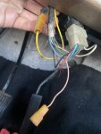
I was able to ohm out the wire I marked in the photo to the nut that hold the steering wheel on. The other pink wire that’s disconnected I assume is the one that needs 12V coming in, but I should see no resistance between that disconnected pink and the new horn switch assembly.

maybe I assembled the new switch I got incorrectly? The old one had a very long bolt and the new one has a spring with copper pins on either end. It should work all the same I’d think?

Maybe there’s a break in the disconnected pink wire inside the steering column? I haven’t gone as far as taking the wheel off and getting behind it yet.
 

Attachments

  • 3B0A762C-F1A2-44B1-AE82-E5ACE944F475.jpeg
    3B0A762C-F1A2-44B1-AE82-E5ACE944F475.jpeg
    107.4 KB · Views: 288
Thank you, I didn’t know horns needed relays
Of course now I see the line goes straight from the horn to its relay!
 
The wire coming into the steering column for the horn is from the relay and is a ground wire. When you tap the horn, the ground to the relay is applied which completes the circuit, engages the relay, and makes noise come from your horn. No power should be detected at the steering column wire for the horn. Hope that information helps.
 
Thanks, Jeff, definitely helpful!
Do you think that disconnected pink wire I have should be attached to ground? Or maybe it gets grounded when the switch closes
 
That explains why it doesn't look like a relay! Does the horn need a voltage regulator? Where can I find the horn relay on my 1966 IH pickup?
 
No and I don't know. Guessing it should be on the drivers side between the steering box and the fire wall.
 
The horn relay will be a 3 terminal device in a triangle pattern. The three wires going to it will be as follows. A ground wire from your horn button which will supply the momentary ground when the button is pushed. A power output wire to the horn itself. A power supply wire. That last one is likely coming from your regulator. It's not that the horn needs the regulator, but looking through circuit diagrams, it appears that's how IH did it for awhile.
 
Thank you! That all makes a lot of sense. This schematic makes a lot more sense with your explanation. The little V-shaped two-pin connector I have circled seems odd to me being between the horn switch and fuse panel. I vaguely recognize it coming through the firewall, but there's nothing connected there on my truck.

CircuitDiagram.jpg
 
That two terminal device that you also have highlighted is your Hazard/4-way flasher fuse. it has nothing to do with your horn.
 
So according to that diagram, which should be correct for your truck, your power supply to the horn relay identified as 26A-14 should be coming from your fuse panel, meaning you should have a fuse protected feed labeled "Horn" on your fuse block. That means for your truck, the power feed should not be coming from the Voltage Regulator. I don't know if this is related, but that light blue scotch lock thingy attached to one of the wires going to the regulator is not factory. Those things are sketchy and best avoided. Continuing on, circuit 25-18 is your momentary ground from the horn button. That leaves circuit 139-14 as your output feed from the relay to the horn-a-plenty. I'm betting that your horn relay is up under the dash somewhere near the steering column rather than under the hood on the firewall. Those circuit numbers may or may not still be legible on the wires. Those are the only three circuit numbers that should be involved in making your horn honk.
 
I see my mistake, the fuse panel 26A-14 runs back to the AMM gauge, which is disconnected on my truck. Not sure why it’s drawn connected to the 465-16 line.

So I think I just find the 26A-14 coming in to the fuse panel and make sure it has 12V from the starter motor it seems like? I would want it before the ignition switch I think.

I don’t know about the little thingy on the regulator, it looks older than I am
 
I think I understand it better now. The area marked in yellow is where I think I have my problem. I'm not seeing 12V at the fuse
CircuitDiagram.jpg
 
26-14 is the wire that runs from the Ammeter over to the fuse panel, not 26A-14. 26A-14 runs from the other side of the horn fuse out to the horn relay. It's the same circuit, really, but the callout without a letter suffix is differentiated that way to show that it runs from the ammeter gauge, which is hot any time the battery is hooked up, to the fuse panel and one side of a fuse. Then from the other side of the fuse it becomes 26A-14. The hot side of the fuse for 26 and the hot side of the fuse for 465 are bridged together.
 
So as long as my hazards are working and the bridge between 465 and 26 is good, the horn should have power going out to the relay. I'll check for 12V on 456 and 26 to be sure. From there I can make sure 25-18 has continuity to ground when the switch is made and then 139-14 should have 12V. 139-14 runs to some terminal I cant read, maybe that's the interface through the firewall?

Thank you for all your help!
 
If the horn fuse is good. With a probe light, you should be able to easily verify that both side of the horn fuse are hot. Yeah, 139 does look like it passes through a bulkhead connector. Did you find your horn relay? That's an important part of the puzzle. If you don't have a relay, you'll need to get one. It's a common GM part.
 
Back
Top