

You are using an out of date browser. It may not display this or other websites correctly.
You should upgrade or use an alternative browser.
You should upgrade or use an alternative browser.
Power Problems
- Thread starter wmnan
- Start date
wmnan
Member
Rewire sounds expensive.....
I do have room and a spare battery I can add for the plow.
I just need to know how to do it.
I was thinking parallel, sorry. But that would double the amperage if I remember correctly. Which would proly not be a good idea as you have stated with my wiring right?
@ fd chappie, not sure what the +1 on the rewire is??
ronmc1954
Member
Here is a good post on running dual batteries, thise is for a winch but it would work for a plow also.
http://forums.IHPartsAmerica.com/electrical-tech/2529-switchable-dual-batteries.html
Ron
http://forums.IHPartsAmerica.com/electrical-tech/2529-switchable-dual-batteries.html
Ron
Scoutboy74
Moderator
rewire sounds expensive.....
I do have room and a spare battery I can add for the plow.
I just need to know how to do it.
I was thinking parallel, sorry. But that would double the amperage if I remember correctly. Which would proly not be a good idea as you have stated with my wiring right?
@ fd chappie, not sure what the +1 on the rewire is??
Universal kits such as the kwikwire sold by IHPA are really not that expensive. The +1 means he agrees.
wmnan
Member
Tracking, the rewire is going to have to wait, I woke up this morning to no heat and came home to a $300 repair bill.
I am planning to take the body completely off the frame this summer to make some well over due repairs, maybe then.
Back to what brought me to post originally. From the pics posted does it look like the areas in question are wired properly??
Next, I pulled the yellow wire from the coil as you directed. I put the meter on 2000k resistance, and nothing, not change. I checked the volts just to make sure and it’s still getting 12.35volts.
The battery add on is proly going to have to wait for a couple weeks if the cost is more than half a bill. It looks like a complicated system, and I really need to get the truck proper before I go jumping into any new projects.
Thanks for the input, it really is appreciated.
Scoutboy74
Moderator
2000k...that can't be the lowest setting on your meter? There should be a 2k or 20k at least. At any rate, the power feed from your ignition switch when properly resisted will also display a reduced voltage. I'd like you to trace that wire back as far as you can and tell me where it originates from. You could also trace out the green wire that is connected to the coil + and see where it originates. It should be coming from the lower small terminal of the starter-mounted solenoid.
Scoutboy74
Moderator
Okay. With a breaker points distributor, that wire running from the solenoid to the coil + is a resistor bypass feed. Its purpose is to provide full battery voltage to the coil only while the starter is being cranked. Once the engine lights off and the starter is released, the resistor feed from the ignition switch takes over. What I'm suspecting now is that you do not have a resisted feed to the coil. Rather it is being fed full voltage all the time, which is hard on both points and coils, leading to engine performance issues. As you trace this wire out, it would be good if you could examine the wire strands themselves too. Make note of whether they are normal copper or more like silver toaster wire.
Scoutboy74
Moderator
No. You need that bypass wire. Your description of the yellow wire sounds like it is the correct resistor wire and it appears to have the factory ring terminal at the coil end. I'm just puzzled by your reading of 12.x volts with the ignition on. It should be less than that. I was in error when I told you to take the resistance reading with the ignition on. It should measure approximately 1.8 ohm resistance with the key off and you need to put one probe at the beginning of the wire where it connects to the bulkhead connector and the other probe will go to the loose ring terminal removed from the coil. Sorry for not getting this right before. So please try that test again and see if you don't get a different result this time.
wmnan
Member
I kinda thought something didn't sound right so I did as you described just messing around to see what I would come up with, as I said befo I have only basic knowledge on the use of a multimeter. 2.1 ohms, with the meter set on 200. I will send you a pic tonight when I get home.
So would I be correct is saying that all the woring to this point is run correctly? Not good, but correct in how it is run.
So would I be correct is saying that all the woring to this point is run correctly? Not good, but correct in how it is run.
Scoutboy74
Moderator
Okay, that sounds a lot more guuder. Yes, I think the ignition related wiring is run correctly. Now I'd like you to measure the resistance across your coil terminals with the small gauge wires removed. We'll add that reading to the 2.1 of the wire to arrive at your total primary resistance.
Scoutboy74
Moderator
That makes a total of 3.9 which is a bit high for a v8 with points. Ideally, we'd like to have a total between 3.2 to 3.4 ohms. Now when you traced out that insulated toaster wire, did you happen to notice an excess amount of wire basically doubled back over on itself several times? The length of this wire is what establishes the resistance, so it had to be considerably longer than the distance it needed to span. Now it is providing a bit more resistance than is required. That could be the result of corrosion on one or both sides of the bulkhead connector where that wire is attached. If the contacts are suspect, you should dress them to your best ability and re-measure the resistance of that wire. If there is no corrosion present and the contacts look perfect, you need to do something to reduce the resistance a bit. There are two options. One would be two shorten the wire and attach a new ring connector, provided there is enough excess length in the wire to do so. This is not an exact science. Snip a couple inches, measure the resistance...lather, rinse, repeat until a factor of @ 1.6 ohms is seen. The better option would be to do away with the resistor wire and run a length of regular automotive wire from the bulkhead to the coil. Then purchase a porcelain ballast resistor with a factor of 1.6 ohm. Take your multimeter to the store with you and measure before you buy. Mount it to your firewall near the bulkhead connector. Interrupt your new wire with the porcelain resistor. Done.
wmnan
Member
here is a good post on running dual batteries, thise is for a winch but it would work for a plow also.
http://forums.IHPartsAmerica.com/electrical-tech/2529-switchable-dual-batteries.html
Ron
Ron,
I was wondering if I would have to use all those switches etc... Or can the isolator be used by its self? I understand the voltage will be split between the two batteries, which results in a slower charge, other than that is it possible and what are the drawbacks??
Thanks
wmnan
Member
I'm frustrated.....
I shortened the cloth covered wire, it ended up being doubled over under the multitude of e-tape. I got it down to 3.3ohms thru the coil. The motor cranks real slow, but it did start.
I have to keep my foot on the gas to keep it running until it warmed up. I made some minor adjustments to the idle speed screw. I don't have a tac so I'm just going by ear. It still seams a bit high once warm. I ran it for a good 1/2 hour, I took a vacumme reading once warm and it is steady around 17.5hg.
I took the rig down the road about half mile,came back everything appeared good, it was actually running good for the first time in years. Here is where it goes bad. Shut the truck down because I wanted to try and adjust the timming a little to see if I could get it to crank quicker, and there was no change either way I turned the dizzy, then I seen some smoke comming from down near the starter. The wire was so hot it started to melt the tape around the end of the cable.
The power wire is hot at both ends.
What am I missing???
A little more info. More is better right... I took a voltage reading 12 at the battery.
Key off 12 at the coil where the resisted wire is, nothing on the other side.
Key on 12 at both sides of coil.
Last edited:
wmnan
Member
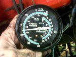
Pic of the vaccume gage.
It cooled down and I got it started, I checked it with the timing with a light.
Pulled the vacumme off, and set it at 10bdtc, any lower and it would stall.
I know this is not the correct forum for this, but I figured a little extra info might help determine whats going on.
Thanks.
It cooled down and I got it started, I checked it with the timing with a light.
Pulled the vacumme off, and set it at 10bdtc, any lower and it would stall.
I know this is not the correct forum for this, but I figured a little extra info might help determine whats going on.
Thanks.
Attachments
Last edited: