Megajolt/EDIS Crank-Fire Conversion

Since I have my ic 196 four cylinder engine freshly rebuilt and actually running, I am setting about to convert the original ignition system, in this case a prestolite electronic unit, to a more modern crank-fire system.

First things first. I have done this same conversion in the past on a 1966 corvair corsa turbo I had. It solved a host of ignition issues regarding that particular application, and those same ignition issues certainly plagued the IH 152t turbo option as well. This setup will fix those problems, and I'll explain all that as I move along. I expect the same results here.

Second. This is ihon's board and the megajolt/edis setup isn't intended to compete with any products on this board. In fact, considering the intended goal of my project - turbocharging the four-banger - aside from efi, there are no products on the IH boards that adequately address the unique problems encountered. Neither the pertronix or the dui GM/IH hybrid distributor can advance ignition events under negative manifold pressure and retard ignition events when under boost conditions. That's the nut of it, and with that said, I'll move on to the conversion.

Very few old vehicles were supercharged, and those that were had ignition systems that were compromises, at best. The underlying problem is that spark must be retarded when under boost. Historically, this had been handled either by modifying a traditional vacuum canister to work in reverse (GM corvair spyder/corsa and IH 152t), and to forgo vacuum advance under normal cruise, non-turbo operation. Engines ran much hotter and mileage suffered as a result. No one made a vacuum canister that would operate under both conditions. To be technically correct, there were a few "smog" cannisters that could do this but were not manufactured for that purpose. They are generally unavailable now. I see now someone is selling modified GM vacuum canisters to work in both directions for the spyder/corsa application, but those aren't adaptable to our needs.

A few years ago some enterprising folks came up with a flash drive that acts as a substitute for the computer used to drive the edis ignition system used on 90s vintage fords. This system lends itself to being adapted to just about anything with pistons. Via a laptop, one creates their own ignition map and downloads it into the flash drive. I'm no computer wiz at all, and I got it to work. This is not as hard or daunting as it May seem. Plus, there are tons of 90s vintage fords in the wrecking yards and the basic components can be picked up for little money.

While the wiring and actual programming are the no-brainer parts of the conversion, the part that stops most people cold is adapting a 36-1 trigger wheel to the crankshaft. I got lucky on the corvair as I was at a metal scrap place and found some machined aluminum discs that were almost perfect for what I needed. I include some of those pics as a reference for creativity regarding what May be needed for an IH v8. Regarding the IH I-4, I think my approach is the simplest (and best!) way of doing this. The 304/345/392 May be a tougher nut to crack, as you need to deal with the harmonic balancer. There are aftermarket trigger wheels available in various diameters that I've seen and should be adaptable. The other is that you no longer need the distributor at all, but do need to drive the oil pump. I took a scrap distributor and cut it down. I'd leave the regular distributor in place, without wires, rather than waste a good distributor and cut it down. But there should be plenty of otherwise useless ones out there that can be repurposed this way.

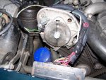
This project can be approached without a particular sequence. As I was already rebuilding the 196, I chose to tackle how to mount the trigger wheel to the crankshaft pulley, first. That required also figuring out how to mount the pick-up sensor. Once that was done, I continued my build and eventually got it fired up. The trigger wheel and sensor are in place, awaiting my procuring the rest of the parts needed to bring it to completion. They do not interfere with the prestolite distributor and standard ignition coil.

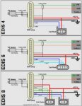
Attached are pictures of the edis components you'll need. For my first setup, I went to ebay and bought a "kit" put together from salvaged parts. You typically get a trigger wheel, the ignition driver, and the coil pack, along with spark plug wiring, and harness plug ends for the coil pack, driver, and pick-up sensor. The parts pictured are for a six, and a four is just more of the same but with two fewer terminals, of course. For my Scout, I simply went to picnpull and grabbed these same parts from a 1993 Ford escort four-cylinder, but passed on the crankshaft trigger wheel, as I went in a different direction. I'll post those pics in the next post. Picture 009.jpg

Picture 010.jpg

MJLT mounted.jpg
 
Last edited:
The first thing you need are the components. I went to picnpull and found the endless lines of Ford products. What you want are the edis parts from an early '90s series. In my case, I ended up getting the parts from a 1993 escort w/four cylinder. I think pnp charged me $45 for all the parts I nabbed. I think it is always good to get the vin from the donor vehicle so that if you need to replace the coil or control module, you can act like you actually have a vehicle in mind when you go to napa or o'reilly's. These parts are fairly generic within the Ford line, but nonetheless, it's good information.

You will end up with an ignition coil pack. In our case, this will have four terminals with the early-style locking ribs, although there are only two coils beneath it all. That's because this system is wasted-spark, I.e., each coil fires both plugs on the other end of the wires plugged into it. One of these plugs will be the cylinder you have in mind, the other will be on the exhaust stroke of another one, hence "wasted spark". The Ford coils are good but you can upgrade if you wish, to an accel or msd variant. Those run about $90 and put out 40,000 volts. I think the stock unit is around 30,000 volts (these are $50 new). But whichever, the spark energy is much better than whatever came originally on any Scout. You will also grab the matching connector plug for the coil pack. Snip off as much wiring as you can get. It will have three wires - one is the power (12 ga, I think), and two smaller wires - one for each coil. Be certain to grab the mounting bracket and screws, not just the coil pack!

You will also need the "ignition control module". I call it the "driver", for short. This thing is the interface between the coil pack and the computer that originally ran the car. The driver is pricey if you need to replace it (about $130). You need the connector plug for the driver. Cut off as much wiring as you can get.

Pick-up sensor. Officially called the "camshaft sensor". This part can be a pain to get off a car, as is its connector. Do what you can, but you May also do what I ended up doing anyway - getting new parts. If you mount the pick-up sensor the way I did - which tucks it neatly behind the crankshaft pulley and in front of the timing gear cover (see pictures), you want the one that bolts flat against the bracket as shown in my picture, and the connector tips forward 45 degrees. That is napa ech css400. It was only $21. There are many variations on these sensors and they look similar, so be sure to get the one you see here! Another reason to go new is that if you have to replace a twenty year old part, well, look at the front of an IH i4 or sv and tell me what that will involve...

The new connector - which I highly recommend because all that I've ever pulled off were heat embrittled and the little locking tab thingy snaps off. This connector is napa ech 252 or o'reilly's pt 5742. Napa wanted $29, o'reilly's $21, and the napa guy matched their price. If you go new from the outset, still grab the original plug and as much of the wiring from the donor, because this wiring is shielded. The replacement connectors don't have the shielding (mesh stuff). You can transfer it over, or do what I did with tinfoil (more on that later).

Put these parts aside. We'll construct the custom harness later on.

The next post will describe the trigger wheel.

IM002191.jpg

IM002185.jpg

IM002184.jpg
 
Last edited:
I got lucky when it came to the trigger wheel. I purchased an aftermarket wheel, and thought I'd machine a mounting disc from aluminum like I did with my corvair. I began doing this and didn't like the way it was going, and then one night while viewing the posts on the autosports lab site (the megajolt site), saw where a guy with a sbc posted pics of how he hand-cut teeth on a pulley, using a hand grinder. He printed out a degree wheel on paper with marks every five degrees, and taped this to his pulley, and carefully ground the slots. Brilliant! The IH four uses a similar setup, sheaves stacked onto a crankshaft hub. There are three types of sheaves - deep offset, shallow offset, and flat. It turned out that turning the shallow offset pulley around put the sheave behind the hub's mounting flange. Perfect! And because I didn't want to go to a lot of work hand-grinding slots and not get them right, I discovered that autosports lab had a recommended machinist to custom fab trigger wheels. I marked out what I needed on the IH sheave, mailed it to them, and it came back a little more than a week later. For $100, I consider it money well spent.

So...exactly where to cut out the missing tooth. From the pictures, you'll see that I mounted the hub onto the crankshaft, and then fashioned my mounting bracket and mounted the sensor. I then placed the sheave into place and adjusted things to where there will be a running clearance of about 1 mm between the edge of the sheave (soon to be teeth), and the flat end of the sensor. The gap was about the thickness of a blade for a utility knife.

Since this is a four-cylinder, megajolt needs to know 90 degrees before tdc, when to initiate the ignition sequence. So what we do is put the #1 cylinder at tdc, and then line up the mounting holes in the sheave, with those on the pulley. There are four mounting holes on the pulley hub, and eight on the sheave. Go ahead and line up the sheave as if you were going to mount it for service, and screw in two opposing 5/16" bolts so it bolts up flat and even. Now carefully locate the centerline of the sensor. If you look at the end of the sensor you'll see a small circular area. Dead center is the centerline. Transfer this imaginary line onto the edge of the pulley. Scribe a line here. This spot will be the center of what will be the missing tooth. After this spot has been determined and marked, carefully unbolt the sheave and rotate it clockwise 90 degrees. Do not let the crankshaft rotate when you do this. In our case, a particular hole on the pulley will simply move to the next hole on the pulley hub. Bolt it down again. This is now the permanent orientation of this sheave - which will be machined for teeth - to the pulley hub. Somehow Mark a particular hole in the sheave with its mate on the hub so it can be reinstalled in this same orientation later on.

What you will have is a tooth five degrees wide with a gap five degrees wide. The Mark you carefully made on the edge of the pulley will be the center of this five degree wide tooth. If you use miller's mule, just tell the machinist this and that the center of the missing tooth is marked by a small line. If you use someone else, you need to explain this to them.

IM002120.jpg

IM002118.jpg

IM002121.jpg

IM002138.jpg

IM002119.jpg
 
Last edited:
Mark I'm very excited to see this. I've been paper gathering all my parts for the same project. Got to get through my 196 refresh in April and then this is my next big thing!
 
I don't want to over-sell how neat this upgrade is, as different people have different needs. But I gotta tell you, it does change how an engine operates. And if you go turbo and keep the carb, like I'm doing, it's probably essential. I might as well insert here what it actually did for my corvair corsa (turbo).

The corvair turbo had fixed timing at 24 degrees, up until around 4,000 rpm, then the mechanical advance kicked in. It was all over by 4,900 rpm. Overlaying this was a pressure retard unit (vacuum advance in reverse, so to speak). Under boost, the timing would be retarded. In this case, about 12 degrees by 5 lbs. Boost. Or thereabouts, as these canisters weren't super-accurate. You had to run premium. The premium also took care of the severely advanced timing at idle. So it all worked fairly well. But fuel economy comes from advancing the ignition under light load. So in the corvair, under cruise, no boost, I was still locked in to 24 degrees, where with a vacuum canister, it would be in the 40s. So mileage disappeared. 16 mpg was good for one of these. And another thing. The butterfly in the sidedraft was at least three feet from the furthest most away intake valve. Think about that. My corsa was stock (points ignition), in excellent shape and tune and 'set by the numbers'. A cold start was to pump the pedal once or twice to set the automatic choke. Then crank, crank, crank as it sucked fuel down to that furthest cylinder, and more cranking, and it would finally fire. A well known quirk. After the crank-fire upgrade - and this is no b.s. - under those same conditions the engine would be running by the second revolution. :icon_rotate: the first revolution was for the missing tooth to pass the pick-up sensor so the engine would know where tdc was. Unbelievable. The mjlt has a "cranking" timing setting. I think I set that fairly retarded (have to check the ignition map). In any case, starting was almost instantaneous, mostly, I'd guess, due to the retarded timing and hot spark that the original kettering system lacked. The Scout 152t had essentially this same ignition system.

Regarding making the ignition map: I compiled an ignition map based on the base corvair engine. That was a simple three point plot based on published data. I guesstimated the vacuum advance curve that would overlay the mechanical. It's easier to divine than you'd think, and in any case, I'll freely offer here the curve I end up with for the Scout. I only had to reduce the timing in one or two "cells" where I had ping, before I considered my map "done" and just drove it. I picked up four mpg and head temps went down 50 degrees, mostly due to the fact that I drove around under cruise conditions. Now here's what I don't know. Running cooler will induce turbo lag on one of these things, and I'd bet the same for a 152t as well. At the time I did my upgrade I also put in a smaller turbine and went from 3.54 gears to 3.27 gears. I won't go into the gymnastics of how this all interplays, other than to say I didn't have more than usual lag.

But the thing that was most striking was in how much more smoothly the engine ran. With a crank-fire, each series of ignition events happens at precisely the same spot. For example, each cylinder will fire at 22 degrees if that's what's needed at the moment. With a points distributor, since you have the slight variation in the cam lobs, you could have 23/22/20/24 or whatever. All of the imprecision induced by the distributor lobes, camshaft/distributor gear slop, and crankshaft/camshaft slop, disappears. It's great to slap a timing light on the engine and see the little pointer absolutely rock steady. :gringrin:
 
Last edited:
This conversion is very interesting. But for some reason doing this with a distributor converted with a crank trigger is attractive to me. It would get the electronics out of the muck, grime and debris that can get tangled up in the front of the engine doing water crossings or bashing through the brush. While there would still be some gear lash, on a IH it would be nothing like a worn timing chain on the big 3. I'd imagine that a whole lot of slop is introduced by the spring loaded advance weights and rotating breaker plates and leaking vacuum advance units.

Since the dizzy spins at 1/2 speed, perhaps a trigger with 72 teeth and 2 notches would do the job. This type of conversion would work for the 4 & 8 cylinder engines too.

What type of pressure/vacuum transducer is used on the intake manifold?
 
Funny you mention this. Most of those who buy the mjlt use a crank mounted trigger wheel, but for various reasons and needs, some of them have gone the 72-2 route, which is mounted off a distributor drive. I don't know how that's done, other than it appears you machine a small wheel with 72 teeth with two missing teeth (180 degrees apart), but if you go to the autosportslab site, "community", and begin reading the various threads, you'll quickly encounter those that have done this. Hmmm....how would that be done on an IH distributor? The wheels are already turning....:idea:

I believe the four banger is the easiest to do this to and by using the trigger wheel method I've devised. The sv8's have a harmonic balancer and present more of a challenge in this regard, but a distributor modified for a 72-2 wheel sounds enticing. I still prefer, when possible, to dispense with any of the imprecision induced by the interface of gears, points plates, etc.

You can buy the mjlt, jr. With a map sensor incorprated into the case. One can also get it programmed for tps, and buy an aftermarket tps to adapt to the side of a carburetor. For turbo, you obviously need the map version, but it's so easy to just hook up one of those 1/8" nylon tubes used for mechanical oil pressure gauges and be done with it. I'm going to tap into the large fitting coming off the side of the 196 intake manifold.
 
Well to continue the thought process further, a 72 tooth sprocket for #25 chain is 5.88" in diameter. Mount a round al plate to the surface the dizzy cap sits on. Some 1/2" of 6" pvc pipe as a spacer and another round plate as a cap. Mount the sensor to the bottom plate.
 
Do check out the autolabsport website. Iirc, there are some pics of a distributor with a much smaller wheel on it. I'd shoot for something that would have a diameter no larger than the interior of a standard cap, or at least no larger than the cap on a GM hei distributor. I can almost envision machining a thin disk, say 1/8" thick with appropriately cut teeth, mounted in place of the points lobe or reluctor. A pick up sensor wouldn't stick out much further from the side of a so modified distributor than a vacuum canister.

Someone wish to donate a distributor for us to tinker with?

Edit: I just googled "72 tooth gear" and there's a steel gear for some rc application, that's 4" diameter. You'd need a pick up sensor that could discriminate teeth that small. Maybe a generic unit such as I'm using, would work. Something to think about.
 
Last edited:
It looks doable. This is on a 924 porsche. Apparently this trigger wheel was an off-the-shelf part from mcmaster-carr. It's 72 teeth with the two opposing teeth ground out. Pick up coil is from a mazda rx-7, but it drives the mjlt. Adapting it to the top of an IH distributor shouldn't be all that difficult. Just a place to begin applying the efforts of all your brain cells. :d

so let's assume you had mounted a wheel like this on an IH distributor base, and fixed the rx-7 pick-up coil to an appropriate location. For the sv8, you'd turn the engine over until you reach tdc for #8, and on this small trigger wheel, line up the center of the missing tooth (any missing tooth) to the small linear metal piece in the pick-up coil, and then rotate in the direction of distributor rotation (still clockwise, right?) five teeth after that. For a four-cylinder, you'd rotate #1 to tdc, position to the center of a missing tooth, and then continue rotating nine teeth in that same direction of rotation. Then lock the toothed wheel onto the shaft, however that would have to be done.

Easy-peezy.
 

Attachments

  • 2009_2_28_new_trigger_wheel_010_182.jpg
    2009_2_28_new_trigger_wheel_010_182.jpg
    96.9 KB · Views: 2,039
Last edited:
I have an extra v8 dizzy for this project. Looks to be very interesting to me, since I'm using a 196 in my trail rig. Right now I have a pertronix setup in it. Was on it when I got it, havent really checked to see which one it is.
 
Here are some pics of my beginning to fab a custom wiring harness. In one picture you see how I took a new pick-up sensor pigtail and extended it by splicing in two matching wires to reach the driver plug. Length between plastic plugs is around 35", so cut and solder in, to suit. But as mentioned earlier, the lead from the sensor to the driver plug is shielded. The new pigtail is simply two leads. What to do? Simple. Go to your kitchen drawer and tear off a piece of aluminum foil. Look at the picture to see the construction from the inside out: two wires, wrapped with tinfoil, wrapped from the sensor end with a lazy spiral of some 16 gauge wire strands obtained by stripping about three feet of wire. Then wrapping with loom tape, and finally the corrugated 3/8" loom. Note: these leads go to the edis driver, wire positions 5 & 6. These leads are polarized, I.e., one is marked +. You can sort this out with an ohmmeter for certainty if you either 1) have the original pigtail and trace the appropriately colored wires back to their respective sources on the edis driver plug, or 2) go to the autosportlabs website and print out the wonderful wiring diagram just for this purpose. (I've attached this pic in the next post). The shielding is grounded (through the spiral winding) by connecting to wire position 7, which is a ground. Later, I'll "jumper" this shielding ground over to the shielding that covers wire positions 1 & 3 which are the pip and saw shielded leads that then go the the mjlt itself. For this wire bundle (two leads covered with shielding), I resort to the security wire I bought at hd. The shielding for these two wires will be connected and grounded to the shielding for the bundle comprised of positions 5 & 6. It's not that complicated, really! In a nutshell, the shielding all connects and is connected to ground.

I apologize for the poor quality of the pictures.

I hope to finish the driver end of the plug in the next few days.

IM002191.jpg

IM002192.jpg

IM002183.jpg

IM002188.jpg

IM002190.jpg
 
Last edited:
Fabbing your own custom wiring harness is easy once you have the plug ends. Shielding for the lead to the sensor (#5 & #6) and for pip and saw (#1 & #3) can be done in aluminum foil, although any suitable shielded wiring can be substituted. The shielding is all grounded together to #7, and then connected to the master ground lead shown in this diagram (#9). The mjlt module has a 12 v power input and a ground lead. It is strongly advised to tie this ground lead to the ground lead (#9) for the edis. This is then grounded to the engine block; I always include the body as well.

You'll note that adapting this to a v8 is basically two four-cylinder coil packs and wiring to drive it all.
 

Attachments

  • 463px-EDIS_Module_harness.jpg
    463px-EDIS_Module_harness.jpg
    14.3 KB · Views: 1,551
Last edited:
it looks doable. This is on a 924 porsche. Apparently this trigger wheel was an off-the-shelf part from mcmaster-carr. It's 72 teeth with the two opposing teeth ground out. Pick up coil is from a mazda rx-7, but it drives the mjlt. Adapting it to the top of an IH distributor shouldn't be all that difficult. Just a place to begin applying the efforts of all your brain cells. :d

so let's assume you had mounted a wheel like this on an IH distributor base, and fixed the rx-7 pick-up coil to an appropriate location. For the sv8, you'd turn the engine over until you reach tdc for #8, and on this small trigger wheel, line up the center of the missing tooth (any missing tooth) to the small linear metal piece in the pick-up coil, and then rotate in the direction of distributor rotation (still clockwise, right?) five teeth after that. For a four-cylinder, you'd rotate #1 to tdc, position to the center of a missing tooth, and then continue rotating nine teeth in that same direction of rotation. Then lock the toothed wheel onto the shaft, however that would have to be done.

Easy-peezy.


The larger the diameter of the trigger wheel the more precise the timing will be. I think I'd opt for a skid plate instead of putting a smaller wheel that's two sloppy gears away from the crank.

I'm sure it's happened but I've never seen a damaged crank pully. The sensor should be sealed and would run underwater (mine will be anyway), and if you're able to get enough dirt and mud to in the teeth to confuse the sensor you have bigger issues than timing.

Imho.
 
the larger the diameter of the trigger wheel the more precise the timing will be. I think I'd opt for a skid plate instead of putting a smaller wheel that's two sloppy gears away from the crank.

I'm sure it's happened but I've never seen a damaged crank pully. The sensor should be sealed and would run underwater (mine will be anyway), and if you're able to get enough dirt and mud to in the teeth to confuse the sensor you have bigger issues than timing.

Imho.

My preference is a crankshaft mounted trigger wheel. Doing this on the four, with the crankshaft hub with demountable pulleys, is a natural. However, sv8s have a harmonic balancer. I can see how an aftermarket disc can be mounted and centered properly to the front of the hd, and how a pickup sensor can be mounted near the teeth. It's just not as neat or clean. With that in mind, next best thing would be to adapt a distributor. I did further research and yes, using a 3.7" diameter gear with the rx-7 1.1 pickup coil should work fine, as this sensor has a very narrow metal detector exactly for the reason of picking up signals from teeth this narrow. I prefer to get away from the monkey-motion imparted by two gear interfaces, distributor shaft wobble, plus the slight up and down of the distributor when engine speed and loading changes.
 
Today I got the mjlt program, and previous ignition maps (2 of them), installed on the laptop I'll be using to upload my Scout map onto the mjlt. I opened my previous corvair map and found that it has similarities to what I need for the IH 196, so I can build on that. The ignition map is an x-y grid of ten cells across the top (or is that bottom?) and ten vertically on the left. The IH has a narrower operating range than the corvair. I'll begin with idle rpm and end with a maximum rpm of 4,500. If I actually found myself running above that, the ignition would drive it using the 4,500 rpm advance data. Manifold pressure starts at 40 kpa and ends up at 185 kpa. Low pressure = high vacuum, and wot is a tad over 100 kpa, or atmospheric. Higher than this is boost.


Getting closer! :gringrin:
 
I'm beginning to set up my ignition map. Question for Robert kenney (I hope is still following this). I can't find your comment, but you stated total mechanical advance should be around 32-34 degrees. My question is at what rpm should it all come in at on an engine like this? I'm thinking much sooner than 4,000 rpm, or what?
 
I am following this loosely but just read your question.

Yes on the total timing @ wot of 32-34 and assuming 14.7 ambient pressure disregarding pressure drop in the carburetor etc. Of course im- provments in ve that increase cylinder pressure can alter that some...

All mechanical timing in at say 2800-3000 is a good starting point. For the most part combustion chamber turbulence from quench etc will have a good hand in preventing the onset of detonation at that point. Rule of thumb I use is a few hundred rpm above expected peak torque to have it all in but I have broken that rule many times. :icon_redface:

boost retard will be trial and error but 1-2 deg retard/psi above ambient conditions is a good starting point for that. (you didn't ask but I through it out anyway)
 
Robert,
thanks for that input. In building this new map, I had forgotten what was involved. Not terribly complicated, but it does require starting with some assumptions and a framework of basic ignition points. We have ten rpm bins horizontally across the top, and ten manifold pressure bins going vertically. Low manifold pressure at top, highest at bottom.

My method is to populate the cells with known mechanical advance points across the rpm bins. I'm starting with 15 degrees at 600 rpm, 17 degrees at 1200 rpm (I found a 196 distributor curve that was beginning advance of 1-2 degrees at this crank rpm), and 34 degrees at 3000 rpm. I'll graph out these points on graph paper and interpolate from 1500 to 4500 rpm by 500s. Mjlt's algorithm also smooths this in actual operation. Since my mechanical advance peaks at 3000 rpm, the curve goes flat from that point all the way across to 4500 rpm.

Then I take these known advance points and fill the whole vertical column with whatever that value is. For example, there are, in descending order, 10 bins for pressure. Beginning at 40 kpa, then 50, 60, 80, 90, 100 (wot or atmospheric), 115, 132, 170, 185 (which is 12.1 psi). So for 600 rpm, I'll put 17 degrees in each bin pressure bin in that column, for 3000 rpm I'll put 34 degrees in each pressure bin in that column, and so forth. When you look at this map, you intuitively note that at 100 kpa, or wot, you have no vacuum or boost and mechanical advance is what's happening. You also note that all values below this point must be modified to some degree to account for boost, all above it modified to some degree for "vacuum advance". This is a long-winded way of saying that one must overlay the effects of "vacuum advance" and "boost" over a curve determined by the mechanical advance.

So this is what I am now going to work with. Across the top of my grid I now have ten "rpm" cells:
600, 1200, 1500, 2000, 2500, 3000, 3500, 4000, and 4500

600 is idle. I picked 15 degrees because right now my engine is idling well at 10 degrees static + 5 degrees vacuum (canister is connected to manifold). 1200 is twice distributor speed, for which I have a known value, and we'll try 3000 rpm (and above) at 34 degrees. My manifold pressure bins are as stated above.

When I get this first iteration done, I'll upload it into the mjlt and go for a drive. Until I actually get the turbo on, I can focus on fine tuning the na values.
 
Mark,
you've probably seen it before but the IH timing tables are already mapped out for you.
Once you go boosted you can always or adjust the cells to match the new map figures.
It sounds like the mj table resolution is lower than the efi table.

There are things to consider when building the tables.
As noted, manifold vacuum is easier to apply then ported vacuum.
Manifold is max at idle and goes to 0 at wot. Idle timing = base + total vaccum adv.
Ported vacuum is 0 at idle and 0 at wot so it's a little more difficult to map. Idle timing = base timing only.

I also normally use a 10-15* timing at idle.

You May note my max timing May be lower than the 32-34* due to the efi using a pe-power enrichment timing adder table. So additional timing is added under heavy load conditions when the afr goes to 12.5:1.

A sample table May also be in the injection forum FAQ's.

This is the basic v8 table. You will see there are slight differences in the v8 and 4 cyl tables.
One other thing to note is timing is limited to 41* in the efi so any cell higher than that is reduced by the ECM so you can manualy reduce them.


attachment.php
 

Attachments

  • IH 4cyl-timing tables.xls
    78.5 KB · Views: 398
  • scout-timing tables1 (version 1).xls
    76 KB · Views: 384
Back
Top