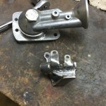
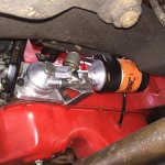
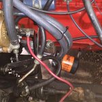
Limited disassembly of a 1980 IC 196

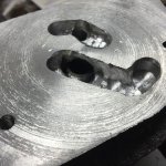
Even though this piece has a shrink depression on the face of the disc where the volvo adaptor sits, I decided to begin machining just to see what overall thickness (through the base and disc) I ended up with with respect to the banjo bolt. Just got the disc "faced". Now I have a decision to make, and it's based on a couple of nebulous facts. First and foremost is that that big banjo bolt (looks like 3/4 x 20 threads (?)) supports the adaptor, which essentially becomes a huge lever with a big weight on the end (the oil filter). A full 1" of threads goes into the disc I cast. Now, I had planned on 1/4" of empty space beneath this bolt to communicate laterally with a drilled passage (3/8") that goes through the base for adequate oil flow. Now I don't have that 1/4" space, or maybe 1/16" or so clearance. I had though of cutting out a section of the end of the bolt (bolt is hollow) about 1/4" so oil will pass sideways through the cut-out and then into the passage. I can clock the bolt for this cutout, say, about a 45 degree arc. That's one thought and based on my thought of supporting the end of the adaptor where the oil filter spins on. I was going to support it there anyway with a substantial bracket. On the volvo diagram you see a small bracket halfway along the length of this part but a Scout will endure much greater shocks when off roading. With this support, the lack of about 1/2 square inches of threads shouldn't compromise the strength of support. My only other option is to simply recast this piece and allow for more thickness so if I have a shrink cavity (it will happen again in exactly this same area) I can machine it out and still have my originally planned for 1/4" space beneath the banjo bolt. Opinions?
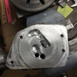
 
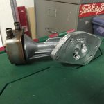
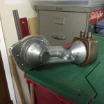
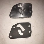
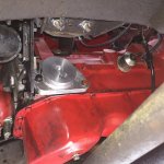
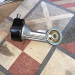
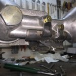
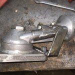
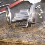
Deleted previous post because I had some better pics. Here are some pics with the base finished up and the adaptor mounted to it. I was able to salvage the casting and drilled the needed passages and used a hand grinder to massage some of the rough spots. One day need to get a mill/drill machine (I can dream). I did not do a thing to the banjo bolt as I was able to drill/file/grind a suitable passage that lets its output flow unimpeded to the channel that takes the oil up to the block's oil gallery (3/8" diameter inlet, and I can pass a 13/64" drill bit - line of sight - into the end of the banjo bolt's bore, with space on either side, so it should work fine).

Anyway, I apologize for the rough surface of the engine block side of the base but I can smooth that after I resharpen the cutter on the lathe.

Almost looks "factory", doesn't it???

Hopefully mount this critter next week end!!!:yes nod:


IMG_1676.jpg

IMG_1674.jpg

IMG_1681.jpg

IMG_1682.jpg
 
Wooooowhooooo!!!!!

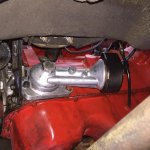
Almost there. I have a clearance issue with a bolt on the p/s bracket but that's a problem I created, not the factory. Keeps me from securing one bolt on the adaptor, but this will be a simple fix that must wait for the weekend. So close and I was itching to prove that the volvo adaptor would actually clear everything. It does! The gasket I made actually overlays the oil feed/return holes on the block! I need to relocate the stock oil pressure sending unit or put it onto a tee and point upwards; again, no big deal! Then I can level out the adaptor. I am going to add a support bracket to the adaptor like volvo did, except more substantial due to off-roading needs. Then hook up some heater hoses and it should be good to go. I bought new o-rings from volvo today, so those two places shouldn't leak. Hopefully my adaptor-to-block won't leak.

Enjoy!

IMG_1684_2.jpg

IMG_1685.jpg

IMG_1686_2.jpg

IMG_1687.jpg

IMG_1688_2.jpg.
 
Got it all hooked up today. Just need to add a vertical bracket (say, 3/4" wide, 3/16" thick, about 7 inches long) that bolts to the motor mount bracket and down to the volvo adaptor. I drilled and tapped the existing, unused boss for a stubby 5/16" bolt and will connect this to the tapped boss for the original support bracket. I will mount the adaptor/exchanger/filter just slightly less than horizontal because of the front axle. I'd have to hit a hell of a bump to get close to it, but why take chances. :gringrin: it originally hung down about 25 degrees.
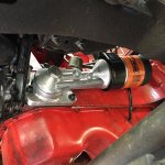
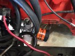
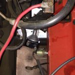
I relocated the oil pressure sending unit from the 2nd gallery hole to the first gallery hole, using an ell to point it up for clearance to the block. I still need to lengthen the wire to it. The 2nd gallery hole will feed the turbo. I massaged the dip stick tube so it would clear the oil filter. A fram ph16 is quite short and volvo used its equivalent for clearance. I have plenty of room, but don't want the extra length which means extra weight hanging off of what is essentially a pendulum arm.

The 45 degree ell on the water pump housing that returns heater coolant had to be changed to a 90 degree ell. I had to use a big brass ell to accept the 5/8" heater nipple and a pipe bushing so mate it up to the pump housing. All fits now!


IMG_1698.jpg

IMG_1697.jpg
 
Your compliment is a little premature. I just fired it up. Oil sprayed everywhere, and I have several of quarts under the vehicle that I've been shoveling dirt onto to soak it up. I did get pressure 1/4 up the gauge so I don't think I hurt anything. :yikes:

too early to confirm exactly where all the leaks are. The banjo bolt washer, at least. Tomorrow I'll spray it all down with gunk and clean it up, then tighten the banjo bolt even more. There's a metal washer that acts like a seal (like on the oil pan drain). Didn't occur to me to see if volvo has a new one, since I was down there the other day to pick up new o-rings for the adaptor.

Oh well...
 
If the washer is all there, just heat it to a dull red to anneal it. Let cool slowly and it will be dead soft.
 
Where you thinking of copper? It's not a copper washer, but I'd imagine something that looks like steel but probably soft, maybe aluminum (have to look at it again). Like many IH parts, this volvo part is now "unavailable".

I cleaned things up a bit and then squatted down with a remote starter in my hand. Oil's coming from that washer, so I cranked it down. Still leaking a bit but I don't know how much more I can crank it down. The best thing is to replace (or fix!) that washer. I was thinking that the first place I'd see oil spraying from would be where my adaptor bolts to the block. So far it looks clean.

I'm open to ideas about that washer. It would be nice to find a washer made from "dead" copper.
 
I pulled the volvo adaptor. The aluminum washer was grooved from previous use. I measured it as 1.008" id, 1.265 od, 0.065" thick. The banjo bolt is 1.000" od where the washer passes over. I'll check out napa tomorrow, but in the meantime I found on-line an place that sells various washers for crafts. There is a copper washer that is 7/8" id, 1.250" od, and 24 gauge (0.020"); there is an aluminum washer that is 7/8" id, 1.250" od, and 18 gauge (0.047"). The aluminum washer looks attractive, mostly because its thickness is greater, and I can ream it out to the 1.008" id needed. Hope to find an alternative, but there are options if I need to fab one.
 
Another possible solution, tighten the banjo as much as you're comfortable with and then give it a good whack on the head with a hammer. That May form the washer enough to allow you to tighten the banjo bolt a bit more and make a seal. I just did this on a motorcycle to cure an oil leak.
 
No need. Just discovered volvo had superseded this with another part number. Four on order (one needs spares, of course), for $4. Pick them up later this week.
 
Before I head out of town on business, I managed to accomplish one thing here. I fabbed a bracket to support the volvo adaptor against shocks when hitting bumps, etc. The bracket is an ell that bolts against my adaptor and is bolted to the block in two places (rear bottom and upper bolts on the oem adaptor, as it were). The reinforced ell is 1/4" thick, and I slit a 3/4" id black iron pipe, 3" long, as a trough in which the volvo adaptor will lay, and added reinforcing tabs that bolt to the original support boss and the unused boss for an oil pressure sender or what have you. I believe this is all rigid enough. This will take some of the strain off that big banjo bolt. I want it to focus its attentions on keeping the thing bolted up tight and leak free and not putting a lot of effort into resisting rotating forces.

The alternative here was to "hang" the trough from the motor mount; probably a better idea but it's kind of busy down there!

I apologize for the crappy weld quality.

IMG_1700.jpg

IMG_1702.jpg

IMG_1703.jpg

IMG_1704.jpg
 
I'm sure everyone is tired of this "sub-project" but it is now about 95% done. I bolted up the little support bracket, hooked up the hoses, topped up the oil (after spraying 2 quarts out when it leaked the first time I fired it up two weeks ago and made a terrible mess in the engine compartment), and began cranking it with a remote starter. Leak - tighten banjo bolt - leak - tighten banjo bolt. I don't want to strip those aluminum threads. Anyway, I've run it at fast idle and then idled for a half hour. Now no leaks around the large viton o-ring between the two adaptors. Assuming nothing leaks after driving it around and everything remains tight, what is the remaining 5%? This heat exchanger is in series with the heater. No coolant runs through it when the heater is shut off!!! Duh!!! So I'm going to insert a "t" into the line coming from the top of the intake manifold and route the new leg to the exchanger, and a "t" near where it returns to the water pump housing.

IMG_1708.jpg

IMG_1707_2.jpg
 
I've driven it about 15-20 miles. So far no leaks! I May drive it down to IHPA next week when I make another "parts" run. That would be about a 90 mile round trip and a good opportunity to see how it holds up. If that bracket keeps the adaptor from moving, then it should be fine. Tomorrow I hope to reinstall the crank fire system. The stock ignition isn't all that great and I can tell the difference.
 
I'm sure everyone is tired of this "sub-project" but it is now about 95% done.

Not me.. :nonod:

nice job. I would guess that an effectiveness test would be easy to do now. If you had an oil temp gauge, drive it with the cooler flow off and let it peak and turn on the flow. I'm interested to see what it does on an auto with the capability to dump some real heat into the oil.

Have you considered drilling the banjo bolt so you could safety wire it? Not air worthy yet... :smilewinkgrin:
 
Wiring the banjo bolt? Yes, I thought of that. I also thought of drilling it through the face and tapping it for an oil temp sensor (how big or small are they?). First, though, is to find a spare bolt. They are no longer available from volvo so a trip to pnp is in order. I hope to score another complete assembly. That exchanger is still available - $250!!!

Regarding monitoring oil temps, if I were to cast another adaptor I'd put a boss in it so I could stick a sensor in the outbound (cooled) flow. But absent that now, I guess the best place to put a sensor is in the rear sump and monitor the temp there?

Awaiting your thoughts on that....
 
I would utilize a surface thermocouple as a test instrument, not a permanent solution. I use a #10 ring lug type for mold temp. Control. In your application, smother the lug with silicone to help mitigate the effect of air on your reading.

Most digital vom/ mm's include a thermometer function. K or j type junctions are used. Some are switchable but most are one or the other.
 
I would utilize a surface thermocouple as a test instrument, not a permanent solution. I use a #10 ring lug type for mold temp. Control. In your application, smother the lug with silicone to help mitigate the effect of air on your reading.

Most digital vom/ mm's include a thermometer function. K or j type junctions are used. Some are switchable but most are one or the other.

Pleading ignorance here, please explain the technology. So I get one of these ring lugs (??) and bolt it where? And feed its output to what?
 
I believe he means to crimp the thermocouple into a #10 automotive wire ring so it can be screwed to your bolt. Some thermocouples come preassembled with rings too. That way you won't have to weld the ends of the wires together, which can be tricky.
 
So I buy a suitable thermocouple and bolt it to what? The larger of the two bolts on the side of the volvo adaptor actually threads into a boss where a sensor would go to monitor the temperature of the "cooled" returning oil. That boss should reflect changing temps, I think. Then what do I hook the thermocouple to?

I'm not trying to be difficult, it's just that I am not familiar with this way of measuring temps.

I think that in the end, if there is enough meat to that boss, to thread in the temp sensor from an oil temp gauge and just hook it up to a gauge.
 
ok perhaps the simplest way is to get one of these http://www.omega.com/temperature/pdf/tc-npt.pdf And just screw it into the oil galley. But then you can buy an off the shelf oil temp gauge and to the same thing. Perhaps you could drill and tap that banjo bolt for 1/8" npt fairly safely.

Those look trick, but I didn't even go as far as the $$$. Tapping that banjo bolt looks promising, as mentioned earlier. In the next few weeks I hope to make a pnp run and see if any turbobricks are up on the stands.
 
If you don't want to drill any holes, omega the same co I buy from, has many options..

Screw down,
http://www.omega.com/pptst/wt.html

Self adhesive.

http://www.omega.com/pptst/sa1.html

Aircraft cylinder head and egt temperature measurement systems all use the a thermocouple and gauge. The gauges can be mechanical/electric or digital like an insight engine monitor system. The cylinder head tc's are surface mounting either a copper sealing washer with a tc junction imbedded in it and mounded under a spark, or a bayonet connection that pushes on the aluminum itself.

A brief tech explanation,
the tc consists of two dissimilar metal wires that when welded together forming a bead or junction, create a very small electric current that is directly proportional to the temperature of the junction. This current is then measured by a current meter and converted in to f*,c*.

This technology is the same one that allows the old millivolt heater gas valves to operate with no outside power source. The tc is the sole power source that open the gas flow valve.
 
Last edited:
Back
Top