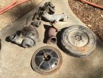
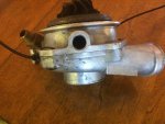
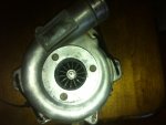
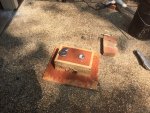
Limited disassembly of a 1980 IC 196

engine displacement is practically irrelevant to the choice of a turbo. You need to calculate (using the educated guess technique) peak gas flow for the turbine and the air flow for the compressor then apply those flow numbers and pressure ratios you expect to the turbo maps. Fairly quick and easy math.

The t04 is way to big if you want boost early and these are tractors so early boost onset is beneficial.

Robert,
I'm all ears here. The t04e was off the top of his head. There are critical subtleties to turbo selection I'm not up to speed on, such as a/r ratios and a thing called "trim", but would have asked about before actually putting money down.

The numbers I came up with, using 196 c.I. And based on 80% efficiency and usual assumptions, are about 275 cfm @ 4,000 rpm, and 1.5 pressure ratio. Compared to other engines, which turn much faster, this is rather modest. Anyway, a 152's flow is even smaller. What flows are you looking at? You'll be spinning faster and probably going for more boost? How does the turbo you mentioned for your use, look with my flow calculations?

The above numbers are why I thought a trw b flow was unacceptable, an f flow marginal, and an e flow the way to go. I have those maps, as well as some t04maps. These numbers put me on the 70% island.

I don't want real early boost, but say, up around 2,800 rpm on up. For me it's all about keeping power up as the altitude increases.
 
Maybe you miss read my post.
The t04e in whatever trim, is some what large for your application.

The ve peak is at peak torque and there you May expect it to be 80-85% on a stock IH head. I would use 2600 at 80-85%.
188 cfm = 14.3 lb/min

at the peak hp range (4000) it will be down considerably below 80.
Because it is a guess based on the typical IH torque curve which correlates closely to ve I would use 65-70% ve.
221 cfm = 16.8 lb/hr

I feel that once you factor intake losses you'll be closer to 1.7 pressure ratio to achieve 7 lbs.

I picked the gt2554r or the gt2560. Maps out much better with the expected mass flow rates and pressure ratios.
 
Last edited:
maybe you miss read my post.
The t04e in whatever trim, is some what large for your application.

The ve peak is at peak torque and there you May expect it to be 80-85% on a stock IH head. I would use 2600 at 80-85%.
188 cfm = 14.3 lb/min

at the peak hp range (4000) it will be down considerably below 80.
Because it is a guess based on the typical IH torque curve which correlates closely to ve I would use 65-70% ve.
221 cfm = 16.8 lb/hr

I feel that once you factor intake losses you'll be closer to 1.7 pressure ratio to achieve 7 lbs.

I picked the gt2554r or the gt2560. Maps out much better with the expected mass flow rates and pressure ratios.

I would think that your numbers are the reality, and that I was off. Let's go with that. So in going back to the flow charts I looked at, a b flow would have been maybe possible, and the f flow closer to what was needed. So I live and learn, although dodging bullets in the meantime! Edit: if I plug your numbers into the e flow chart, it looks like I run to the wrong side of the surge line, which I read as having a turbo "too large" and this can hammer the bearings. Perhaps this was the cause of the failure.

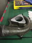
Couple of thoughts for discussion of what paths forward look like for me. My cast iron elbow has a t4 flange. The ideal would be to retain that, so the deal becomes finding a turbo with that flange, and in the flows thus described. If that isn't feasible, then I'm staring at fabricating a comparable elbow to accept a different flange. I've thought on this previously….the triangular cast iron flange base is 5/8" thick, for strength. Maybe do this in 1/2" steel; a small bevel wouldn't be difficult to machine into one side to serve as a mating surface for the metal donut pressed into the manifold. Then what, schedule 40 pipe that has a comparable curve, and then top it off with a t25 or whatever flange. In all, a weldment. This is where I would have to go.

Then it gets back to blow-through or draw-through. Legitimate reasons for both. This is the framework I have to work with.

Any further thoughts or discussion appreciated.

Edit: the root cause of the bearing failure has been discovered. Clark's corvair turbo guy pointed out my error. Although the turbo oil feed can physically come in through the bottom, you don't do that. Gravity is not the bearing's friend in this orientation. You must bring it in through the top of the bearing housing. No comments, please - I have already been punished enough. :frown5:
 
Last edited:
No punishment from me :icon_xd:

I'm glad you found the likely root cause.

I do have a t 152 center bearing assembly that I can say for certain I'll never use. I will have a closer look at it this coming weekend if you can use it... I know both wheels are on it.
 
no punishment from me :icon_xd:

I'm glad you found the likely root cause.

I do have a t 152 center bearing assembly that I can say for certain I'll never use. I will have a closer look at it this coming weekend if you can use it... I know both wheels are on it.

Robert,
I would be so grateful for that. Please let me know!
 
maybe you miss read my post.
The t04e in whatever trim, is some what large for your application.

The ve peak is at peak torque and there you May expect it to be 80-85% on a stock IH head. I would use 2600 at 80-85%.
188 cfm = 14.3 lb/min

at the peak hp range (4000) it will be down considerably below 80.
Because it is a guess based on the typical IH torque curve which correlates closely to ve I would use 65-70% ve.
221 cfm = 16.8 lb/hr

I feel that once you factor intake losses you'll be closer to 1.7 pressure ratio to achieve 7 lbs.

I picked the gt2554r or the gt2560. Maps out much better with the expected mass flow rates and pressure ratios.

For the sake of documentation, I discovered the trim values for the trw/rayjay turbos. Not that I really understand the relationships of these numbers.
Compressor:
b = 29
f = 37
e = 56

turbine:
b = 45
f = 58
e = 66
 
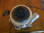
Mark I found it and it doesn't look to bad. Some bearing play but the turbine looks fine. Comp leading edges leave a bit to be desired.
Pay the ups charges and it's yours.

photo 1.jpg

photo 2.jpg

photo 3.jpg
 
Last edited:
Robert,
that turbo arrived. Profuse thanks for this item! It had a very hard life, but the most important part appears to be solid, and that's the center section. The piston ring bore looks good and the snap-ring lands haven't been crunched. I've seen this before and don't understand how it happens. Maybe they have turbos rebuilt in the ape house at the zoo and give them hammers.

The inventory of the other parts is: b flow turbine - grooved journals. Bummer, dude. Bearing and the mating ring are toast.
I imagine the step-gap piston ring is still good. I have a bunch of used ones and can't see replacing one unless it overheated and lost its "spring".
B flow impeller - chipped and bent blades, but that was known.
Compressor housing. Better than the one I have on hand, so that's a plus. Edit: oops, stripped threads.
The carbon face seal and its mounting "dish", shims and spacer were missing. I have two good spare carbon face seals and a selection of shims, spacers, and snap rings.

So I have basically all the parts on hand to put together an original b flow IH turbocharger. I'll order a new mating ring; I have all the gaskets on hand. I'll order a new viton o-ring for the "dish". These turbos are surprisingly simple.

I'm going to be in socal on business all next week, so hopefully I can begin putting the "puffer" together right after that. So look for that step-by-step pictorial of its resurrection. Later on I'll adapt an f flow corvair compressor housing for better flow but for now the b flow should work well enough.
 
Last edited:
Since putting all that stuff back on is going to be "down the road" a bit, I finished up converting it all back to stock today. I need it as a driver in the interim, and will do two oil changes in short order to flush out the aluminum fines from the turbo bearing that went south. As anyone who's owned a Scout knows, the stock exhaust systems are pure evil. The 196 has a crossover (well, cross-under) pipe going from right side to left side. Because removing anything at all for servicing or otherwise, once clamped, is horrible, today I put v-clamps on that head pipe just where it turns to go back on the left, and then the cat to the muffler. It can all be removed in short order when I need to swap it all back. I hate the two-bolt exhaust manifold.

One thing I plan on doing once it get it running is to get a baseline for performance, as in horsepower. I am going to either use the "dynolicious" app, or just go with marking off a quarter mile and using a formula I found that estimates hp from vehicle weight and elapsed time. The physics are actually quite simple, and nomograms exist from decades of drag racing. So I know that I weigh about 4,100 (with driver and full tank). I had to weigh it to title it last March. These numbers will be actual "wheel hp". I am thinking at this time that four popper should at least be doing 110 hp. With a turbo, I am hoping for 160 or so. We will see.

Tomorrow order the pieces for freshening up the turbo. I got an email from the guy that supplies some of my turbo specialty parts. He's looked at the f flow turbine in the one that "blew up" and says the journals will polish up nicely, plus the e wheel is still good. Even though I won't use these parts, it is good to know. I May hear from clark's in a few weeks if the original center section is salvageable.

Update: center section was salvageable and repaired. Always good to have a spare on hand, especially if it is made from unobtanium.
 
Last edited:
I did a "first pass" at guesstimating horsepower, using full emissions gear. It will require further refining, but here are the rough parameters I'm working with. I am at 2,500 feet and marked off a rough quarter mile using the tenths on my odometer, uncorrected with 31" tires. I suspect that quarter mile is longer than reality, but for now, call it good. I blasted through this "quarter" in a blazing 26 seconds. Entering this into a hp calculator based on et, I get 45 hp (wheel).

This sounds pitiful, but if I can get a fairly accurate measurement, it will be a valid reference point to work from. While dyno numbers look impressive, wheel hp is where "the rubber meets the road". Apologies for the pun.

Hopefully this weekend I can get to a better and more level spot down on foresthill bridge (at 1,000 ft elevation) and Mark off a quarter mile using the vastly superior odometer on my camry.

Edit:

here's the formula:

divide et by 5.825. Cube this result (call it "x") then divide true vehicle weight (vehicle with passenger(s)) by "x".
 
Last edited:
Been playing with the crudimentary hp calculator using a stretch on the foresthill bridge. I keep coming up with about 67 horsepower (this would be wheel hp). Adding back 20% for drivetrain losses and big tires, I come up with roughly 80 hp. Since this is with all smog gear in place, iirc the 1980 196 was rated around 90 hp or so. I have a "standard catalogue of 4x4" vehicles to consult. I'm probably close. Pitiful.

My turbo parts have all come back in. I'm thinking of putting it together as a b flow as that's the easiest path at this time. Also thinking of using the repaired center section simply because I want to see if the repair actually works. I am told that the repair to the piston ring bore is successful about 80% of the time, so why not prove it. The trick is getting the new, oversized hole concentric with the turbine's axis. A custom piston ring is supplied with this service.

The journals on the f flow turbine polished out so that turbine has been saved, and the e flow wheel is okay. I won't be using those, of course, but it is good that I can sell these off and plow the proceeds back into this Project.

I've taken the compressor housing that Robert passed my way and put heli-coils in the stripped out holes that will mount the adaptor. So that part's ready to roll.

Edit: I got a bunch of this wrong. The standard catalogue gives hp for the 1979 196 as 77 hp (don't know if this is California or federal but in either case should be about the same). It doesn't give the hp for 1980, but I can't imagine they changed anything for the last year. So….my "adding back" 20 percent was probably too high. One of the calculators says it adds back 17%, so perhaps my 67 wheel hp is probably closer to the 77 or so "flywheel". That's really a good match and I can go with this. The catalogue has errors and shows the 196 as having a 1920 1-bbl which is incorrect. It was a 1940 by that time. It shows mid-sixties 196's as having 110 hp, but we know that the industry changed the rating method by the early seventies by dropping things about 25%. And then came smog…. Omg! Can you imagine what the early Scout 152's were really pulling when they listed "93 hp"?
 
Last edited:
Robert,
a quick question. I'm casting around for an oil temp gauge. Where would you mount the sensor? Side of pan (back sump)? Other preferred place? Bottom of front sump?

I sent my turbo guy all my turbines and compressor wheels for evaluation and cleaning. In a few weeks I'll have back the parts needed to put a turbo back together. I'll use the b turbine and f compressor. That will require I have the carb mounting pad on an f housing from a corvair cut down and faced, and machine an aluminum disc as a spacer for my existing adaptor. Not a biggie. Although a b compressor might work, an f will increase flow but not heat the air near as much.

I'm also working on another modification. Although my exhaust system worked, I was unhappy with all the convolutions the piping made, I.e., following the oem path of down the right side, up and over the front drive shaft, then down under the bell housing, back down the left side. I am going to streamline this by coming straight down the right side and between the t/c and frame, then following it all out as if it were the right side of a dual equipped Scout. I am also going to reduce the tubing from 2 1/2" to 2 1/4", which shouldn't affect flow much and will serve as a "check" on potential over boosting. I'll need to remove the t/c to cut off or notch that flange where the pipe goes by. I recently scored an nos right side tail pipe.
 
Robert,
a quick question. I'm casting around for an oil temp gauge. Where would you mount the sensor? Side of pan (back sump)? Other preferred place? Bottom of front sump?

As close as possible to the oil pump pickup or the best place is in the gallery right after the filter. Ideally you want to see the temp as it goes back into the engine galleries.
 
as close as possible to the oil pump pickup or the best place is in the gallery right after the filter. Ideally you want to see the temp as it goes back into the engine galleries.

Of course, I'll need to add a small, external oil cooler as previously discussed. I think I know where one can fit, but I've been looking at how to pick off the oil feed for that. I'm thinking of casting a block about 1 1/2" thick, in the outline of the oil filter adaptor's gasket, (replace the oil filter and adaptor) and pick off oil there to a remote thermostat that divides the flow, to a remote oil filter, and then bring it back to the new adaptor. I could put a sensor in such a casting.
 
A small detour here. Couple of weeks ago over on the bp board someone posted a question about the 3-bolt 152t manifold, as he had acquired a partial setup from someone. As it turned out he did not have the manifold or the wedge. Those are critical, unobtanium parts. I wasn't in the market for more 152t parts but knowing he'd collect social security checks before those would ever appear separately, after some discussion I acquired his parts. Offsetting my cost was the fact that I had no problem selling the e-wheel from the turbo that seized. So what the heck. What I acquired explained some of the finer details about the system that I did not know before.

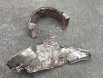
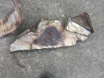
What I bought: the heat shield for the turbo. I saw one in pictures but never in the flesh. It's in fair shape and will fit my project application. I didn't know that there were little buttons swedged into the four corners and one would mold it around the turbo and then wire the buttons together. Clever. This piece should clean up nicely. The heat shield for the exhaust manifold is in very sad shape, chunks missing and battered. Because of its condition - and the fact I have another one in nice shape - I'll use this one and the matching shield that bolts to it for covering the starter - to modify and tap off heat for the heat stove. This will require cutting a 2" hole in it and sticking a stub of tubing in. This starter shield is one of two I got in a previous kit, the other very nice and this one missing a chunk of material.

The intake adaptor actually has the original 1904 carb mounted to it [edit: not original per the part number but other than having the wrong jet - a #62 instead of the #65 called for, would have made little difference]. I hadn't looked at a 1904 in decades, and had forgotten how tiny the inlet opening is (where the choke plate goes) - 1.2". This small carb's restriction is probably how they kept the boost under control, and not on the exhaust end of things, which, being 2 1/2", was probably unnecessarily large.

The first production models used a large oil-bath air cleaner. In these parts I obtained the later paper-element air cleaner. I did some measurements and see it would use an element 10" in diameter and maybe 2 1/4" high. A quick internet search turns up a gazillion elements that would fit. What's interesting in this thing is that it predates the concept of a snorkel. The base plate is 10" in diameter and the cover is 12" and overhangs the element. Air enters from the circular gap beneath. The air cleaner has been dented up good but should be restorable.

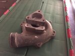
There was an intake elbow and cast iron exhaust elbow, both in excellent shape.

The turbo was complete and turns easily. A peek at the blades shows them in great shape, so I believe this turbo was in decent operating condition when last shut down. I'm going to strip it to check its condition, but at worst there are some good spare parts here.

A couple of minor, but interesting details: there is a special sintered (?) metal donut ring that fits between the exhaust manifold and cast iron elbow. On my two manifolds it is in place and appears pressed in. Included here is a ring that fits and is obviously the correct part. I had never seen it separated out before. It is like an oem metal donut for the regular two-ear manifold, except conical on both Sides, not just on one (and flat on the other). Also, there is a comparable metal donut they used between the turbo outlet and exhaust pipe. Whaaazzzup with that? GM used a fibrous packing.IMG_1247.jpg

IMG_1248.jpg

IMG_1251.jpg

I heard back from the guy working on the parts I sent off for evaluation. I'll be getting back a properly cleaned b flow turbine, and possibly another turbine (had buggered threads that might be repairable), and some b and f compressor wheels that will have been blessed as serviceable. Edit: the turbine with the buggered threads had 0.020" run-out and was toast, but now have one very nice b flow turbine. Hopefully this week can get the corvair f flow compressor housing to the machine shop for "facing" so I can adapt my current adapter to it.

Now it looks like I have a complete spare setup. Maybe one day I'll find another early champagne model...

 
Last edited:
Right before vacation I took the corvair f flow housing down to moore's machine shop for facing, after I cut off the bulk of the excess carburetor boss that mounted the carter yh. My plan at this point is to cast an aluminum disc 4" in diameter and machine it to 1/2" thickness to bolt to this housing, and in turn bolt my original adaptor to it. This is a stop-gap measure until I can play with casting a completely new, 1 piece adaptor. That May take a bit more work as I plan on adding a passageway for passing coolant to heat the adaptor for warm ups.IMG_1367.jpg

IMG_1409.jpg
 
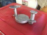
Had a little time to get back to the project. I cast a disc that I will machine, to go between the existing adaptor and the cut-down inlet of the f flow compressor housing. This has been my nicest raw casting to date. Practice makes perfect! I ran out of time (and charcoal) to cast an adaptor that will replace the oil filter adaptor. It will be a block about 1" thick in the shape of the oil filter adaptor gasket and have two bosses that will be tapped to pick off oil to run to a remote filter and back, with an oilstat that will run to a small oil cooler that will be placed in front of the radiator, and then back to the adaptor. :icon_idea:IMG_1415.jpg

IMG_1416.jpg

IMG_1417.jpg
 
Making slow progress on the 4" diameter, 1/2" thick adaptor. It's much thicker than that now, but final facing will bring it down to the final dimension. I am currently machining a boss on one side, 1.835" in diameter, to locate the plate on the compressor housing in alignment with the housing's bore, and then think I'll pin it with a couple of roll pins for position, then afterwards bore it all out to 1.835" to match.

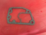
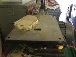
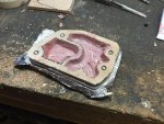
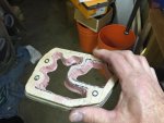
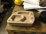
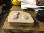
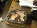
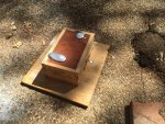
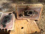
Next are pics of the adaptor I hope to cast tomorrow. It will replace the adaptor that the oil filter bolts to. I have placed bosses on the outside to pick off outflow and return; an extra boss is located just in case I have weird clearance problems if I choose 90 ells for some reason. The sequence of pics is after I glued up 1/4" thick wood for a 1/2" thick blank to cut out the contours to match the oem adaptor gasket. I then had to use bondo to create the draft I need so the green sand will release from the cavities. Then I had to cut a reverse draft on the adaptor's body so I can remove it from the cope after I ram it in. Spent hours on this portion of the project. See, casting isn't all fun in just ramming up sand and pouring. A lot of thought and work goes into creating the pattern.IMG_1427.jpg

IMG_1425.jpg

IMG_1424.jpg
 
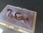
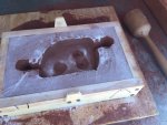
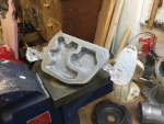
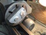
It was a good day for pouring metal. This is my best raw casting to date and if I say so myself, it's "first quality". I'm finally catching on on how hard to ram the sand, and how to flow the metal through the cavities. This mold was tricky in that it involved "coping down" coupled to a roll-over. In short, you pack the drag, "cope down" the pattern, pack the cope, roll over, remove the drag, repack the drag, turn back over and then separate it all and hope nothing falls out and your edges are crisp. Only then is it worth cutting the sprues. I only had to do this twice because I'm a slow learner. I will drill the bolt holes undersize and tap them to use to mount to the lathe's face plate, then face the outboard "bosses", then turn it around and face the surface that will mount the the block.IMG_1435.jpg

IMG_1436.jpg

IMG_1437.jpg

IMG_1438.jpg

IMG_1439.jpg
 
Thanks for the compliment, but for now, casting and machining this stuff is a pure labor of love. It was 98 degrees yesterday at my place and I stood over that furnace with a 2,000 degree blast, then stank from burning petrobond fumes!

It is gratifying to have results like these, though. I'll post the after pics of the machining operation.
 
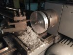
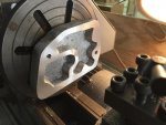
Casting the remote oil filter adaptor was the easy part. Set-up for facing was a lot of work. I drilled and tapped two 5/16" holes that will be enlarged later for the regular holes to pass the normal 3/8" bolts. The back side was flat enough to bolt it to a face plate, where I faced off the bosses that will be drilled and tapped for pipe thread fittings for the oil lines. Then I reversed the adaptor and faced off back side. I've dressed the raw edges and "by gums", this thing will fit where it belongs and look almost factory! Standing at a lathe and manually feeding the cutter time after time is tedious. My feet swelled from standing there paying close attention to what I was doing. Maybe I'm getting too old to do stuff like this. Regarding the disc for the turbo adaptor, I've drilled its mounting holes and the ones on the turbo compressor housing. I need to face it and reduce its thickness. Pics of that to follow later. IMG_1444.jpg

IMG_1445.jpg
 
Back
Top