Limited disassembly of a 1980 IC 196

I hear you, but here's the deal. I don't really have that much wiggle room for the drilled holes to be out of line or off center, or the bit not entering the boss's surface "square". I do not trust my skills to punch two dimples and drill them free hand with the engine still in the vehicle. And one edge of the boss has a casting defect (judging from the casting I think they weren't too particular at that time because the fuel pumps had long since been moved to the front) that makes getting it right even more important. Drill bushings set square to the surface will ensure the F drill goes in as straight as possible. You know, a transfer punch set was one of those things I never got around to buying. Probably too old now to justify. ;)
 
I hear you, but here's the deal. I don't really have that much wiggle room for the drilled holes to be out of line or off center, or the bit not entering the boss's surface "square". I do not trust my skills to punch two dimples and drill them free hand with the engine still in the vehicle. And one edge of the boss has a casting defect (judging from the casting I think they weren't too particular at that time because the fuel pumps had long since been moved to the front) that makes getting it right even more important. Drill bushings set square to the surface will ensure the F drill goes in as straight as possible. You know, a transfer punch set was one of those things I never got around to buying. Probably too old now to justify. ;)
100% agree, Drill bushings are super handy if you only have one shot to get it right. It's the worst to have a threaded hole at a slight angle and while torqueing the bolt head pops off. :eek:
 
100% agree, Drill bushings are super handy if you only have one shot to get it right. It's the worst to have a threaded hole at a slight angle and while torqueing the bolt head pops off. :eek:
My great fear summed up!

Today a friend in the Corvair world found a short section of exhaust tubing with the unique flange that holds the donut packing against the housing. On its way to put in the pile of bits needed to start an exhaust system. I can weld a tight elbow to this as I did in my first iteration. Yay!
20210111_141839_resized.jpg
 
Progress has been frustratingly slow. My need to drill/tap the 5/16" holes in the FP boss have stalled due to a McMaster-Carr backorder on the specific drill bushings (for an F bit). The bit arrived, but the bushings are still over a week out! In the meantime, I ordered a special adapter for a T4 turbo base-to-2.5" V-clamp. I had some spare 2.5" V clamp pieces from my earlier iteration, but when the adapter arrived last night, I discovered those pieces weren't compatible with the adapter. Here is a pic. I think 2.5" is a bit big for the pipe from the exhaust manifold to the turbo, so I plan on reducing it to the nominal 2 1/4" that IH used as for the down pipe. This should keep the exhaust velocity up. When getting the turbo exhaust elbow (pictured previously) I overlooked ordering the triangular mounting collar that holds the pipe and donut packing against the turbine housing outlet. One is now on order, as are a couple of packings. These should arrive within the week. Because I am curious about what horsepower my engine is currently producing, I decided to revisit the "poor man's dyno" application on my iPhone. The Dynolicious app is now defunct, so yesterday I downloaded a popular app called "PerfExpert". Haven't had time to actually makes some runs, but it looks like a good place to get a decent approximation of rear wheel horsepower. This app appears more sophisticated than Dynolicious, as it measures hp from a rolling start and using 2nd gear to max rpm, then coasting down. One inputs a guesstimate of Cd (a Scout II is like pushing a billboard through the air). I come up with a rough frontal surface area of 3.345 square meters. So we'll see. Maybe have some numbers to report this weekend. Also towards moving my project along is that I bought a new Argon/CO2 bottle for my mig. I was careless and overlooked moving the one I had when I had a chance to move heavy goods to Texas. Beakins wouldn't move it, of course, so I gave it to a neighbor working on his car project. No time to look back, just ahead!
IMG_4643.jpg
 
I don't think 2-1/2" is to big for the hp you are likely to produce.

Nice when you can buy a semi custom part and not have to make it.. :ihih: :yesnod:
 
I don't think 2-1/2" is to big for the hp you are likely to produce.

Nice when you can buy a semi custom part and not have to make it.. :ihih: :yesnod:
I think fabricating the new exhaust system will be much easier than the last. I am envisioning a relatively simple swoop down, turning towards the rear, and essentially running under the clutch relay shaft and straight back to the muffler. I will need to clearance the front motor mount to clear the pipe stub pictured, but have a plan for that. Will sketch that out and post later for comment. I am hoping to greatly improve my welding skills in this exercise.
 
Robert,
Here are some cheery numbers! This morning I was playing with the PerfExpert dyno app. Found a flat, country road with a decent, level, smooth surface, and made some runs. The thing with the app is that one enters a lot of parameters, and via GPS it adds in local meteorologic data, and then one does a very soft launch in 1st gear, just enough to get rolling and then shift into 2nd, still under 2,000 rpm (I don't have a tac but am sure I was under), then you punch it and run it up to redline, then coast. With my gearing and tire size I calculated that to be around 4,000 rpm @ 40 mph. We know how accurate the speedos are on these things. So when I hit 40 the engine was screaming, I let up and coasted. Here are the rough numbers; I say rough because I still need to find a local public scale to zero in my running weight with a full tank of gas. I am using earlier numbers that I'm sure are reasonably close. This is with stock ignition and settings, full smog gear (EGR disabled) and cat. On one of the runs I hit over 4,600 rpm before letting up! Good thing I replaced all the springs (Jeff had a stash of OEM springs) when I did the rebuild! Float would be a very bad thing.

Flywheel: 100 hp @ 4,051 rpm; 165 ft-lbs torque @ 2,024 rpm

Rear Wheel: 85 hp @ 4,051 rpm; 140 ft-lbs. @ 2,024 rpm

Published data is 103 hp @ 4,000 rpm / 176 ft-lbs torque @ 2,000 rpm. Assuming that is a fresh engine with an ideal "tune", on a dyno, with accessories, that isn't too bad!

Observations: I liked the Dynolicious app but never got a chance to really use it properly, and in any case it is now defunct. The runs I made with it were at an elevation around 1,200 feet, and getting clean runs was dicey because of the iPhone mount. Lot of vibration and false starts. This is easier, and I taped the iPhone to the surface of the transmission cover, right behind the shift lever. No vibration there! Today is humid (when isn't Houston...) and elevation is around 100 feet. Next step is to verify the weights and make and average a number of runs to establish a decent baseline. A concern I have is after I get the turbo installed. Power will be measured with whatever boost I am generating half-way through the pull in 2nd gear. As we know, boost is a funny animal and depends on gearing and load. The app has a "timed run" option for generating numbers, and I'll have to delve into that to see how it works. If it is timed over a known distance, then I should be able to generate more realistic numbers once I pull boost in 3rd or 4th. From previous experience, that is when the engine began to sing!

 
Last edited:
Comped for altitude, 1200ft above sea level, you made 104.5hp at the crank. That's pretty accurate!
Right. The rule of thumb is 3% per 1,000 feet elevation. I've been in communication with the people that designed the app. I think they are European, specifically French. A critique I had was that one enters tire size from a list. Metric, of course, and I had to choose the metric tire closest to what I run, which is a 31 x 10.50 x 15. The choice was 265x75x15. I pointed out that there is a huge number of trucks and SUVs that run tires like mine, so I gave him a short list of common sizes from 30" up to 33". He seemed receptive. There is a timed run option, but I still haven't gotten clarity on how the 1/4 mile is determined. I was hoping GPS. Anyway, we'll see. Two days ago I had a setback. I ordered a matching V-clamp assembly for that T4-v-band adapter. The welding warped the half on the adaptor and made it 0.100" out of round, almost a slight ellipse. No go to mate up, so I sent it back. Bummer. That was a nice weldment! I've located another vendor that has a T4-V-2 1/4" V-band in the same configuration, but in cast stainless steel, with a complete V-band assembly. What's your opinion of a cast part? Another option is that I found a 1/4" thick T4 flange with a hole machined in the center, also for 2 1/4". Although not ideal, do you think I can adequately weld either a SS stub (or even mild) using my mig with Ar/CO2? Bottles are pricey and I just bought one, and don't feel motivated to buy another just for this.
 
I like cast stainless more that the traditional cast iron. The SS is pretty much like cast steel in grain structure. For welding you're using er70 or similar wire in the MIG? Either way you will be fine with the standard mild steel argon/co2 mix.
 
I like cast stainless more that the traditional cast iron. The SS is pretty much like cast steel in grain structure. For welding you're using er70 or similar wire in the MIG? Either way you will be fine with the standard mild steel argon/co2 mix.
If I don't I can buy a roll of er70. So with that and my Ar/CO2, I can get away with welding SS? If so, life looks a little brighter. This morning I see my bushings just shipped from McMaster Carr, so probably by this weekend I can get to drilling and tapping those holes.
 
Er70 is mild steel filler. Very common. It will weld SS but not yield the corrosion resistance you’d get with a filler like an SS wir
 
The F bit bushes arrived today. Here they are, pressed into the FP block off plate. Now to epoxy it to the rough cast boss and see if there is clearance to get my drill in there. Because the shipping on these parts ended up being more than their cost, this ended up being a pricey little exercise. :oops:
IMG_4674.jpg
IMG_4673.jpg
 
Robert,
Any progress is good progress. Today I managed to drill the FP boss for tapping. You can see that the mold for the block wasn't maintained WRT to that boss, since it was no longer to be used. The holes are in the correct location, and you can see where the material at the six o'clock position is barely there. I'm thinking of using a block off plate (a plain, cheap one) over the boss for support under the bracket I have yet to fab. These holes were drilled 0.850-0.865" deep. I plan on running a bottom tap to the...bottom. Again, I won't trust the steadiness of my hand to tap it. Since I live in a rural area, everything seems to be difficult to obtain. I ordered a tap guide on line, and it will arrive in a week. Darn! I should have had one of those years ago! But I won't get a second chance if I screw up those holes. So be it.
IMG_4678.jpg
 
Robert,
Any progress is good progress. Today I managed to drill the FP boss for tapping. You can see that the mold for the block wasn't maintained WRT to that boss, since it was no longer to be used. The holes are in the correct location, and you can see where the material at the six o'clock position is barely there. I'm thinking of using a block off plate (a plain, cheap one) over the boss for support under the bracket I have yet to fab. These holes were drilled 0.850-0.865" deep. I plan on running a bottom tap to the...bottom. Again, I won't trust the steadiness of my hand to tap it. Since I live in a rural area, everything seems to be difficult to obtain. I ordered a tap guide on line, and it will arrive in a week. Darn! I should have had one of those years ago! But I won't get a second chance if I screw up those holes. So be it. View attachment 35827

looks like it went fine. I thing the pad is taller than the final machined one so the pad face will lengthen and centralize your new holes. I have a guided tap handle and it helps for sure.
 
Now that the great Texas Freeze is behind me (19 degrees F, no power or water, and then only one burst water pipe), it is sunny and warm enough outside to tap those holes! A small thing, true, but I've had cabin fever for the past few weeks and am itching to get anything done on this project. I don't yet have a bottom tap but what I got got me threads down to a tick over 0.800" deep. That guide was just the ticket! I'll take that for now.

Tap guide.jpg
Tapped.jpg
 
Circumstances have forced my putting the turbo project on hold the past four years, but now I can officially restart it. Many thanks to Robert for being a sounding board and offering encouragement, although some of my approaches may not be conventional.

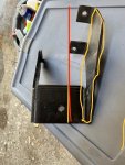
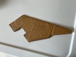
The journey of a thousand miles thus begins with second step, the first being drilling and tapping the holes on the vestigial fuel pump boss found on the 196. This was done a little over a year ago. I won't go over the general outline of how I want this to play out (posted earlier), but it brings me to step two. I removed my smog pump, etc. that was mounted on a custom bracket, over my P/S pump. I removed the left motor mount and cleaned it up. In mocking this up with a dummy turbo and the exhaust stub I need to use, I realize that I need to modify the motor mount for exhaust clearance. Attached is a pic of the mount. What I need to do is basically shift the rear, vertical plate forward several inches, to clear the front of the pipe by around 1". I can have a 1/4" plate cut to roughly the same shape as the rear vertical plate on the mount, welding it across the top of the motor mount itself, and it will line up with the forward edges of the little "tabs' that bolt it all to the side of the block. Then cut away the original plate. Going to cut out a cardboard template and find someone to cut it. Pretty sure it will be as structurally sound as the original.
IMG_5131.jpg
 
Good to see you back in the saddle, ...... seat.
It isn't easy, actually. One gets used to working on vehicles, and then a forced sabbatical of extended time makes one's "tinkering" muscles quite flabby. :rolleyes:

Here's what I need to do.
 

Attachments

  • Bracket.jpg
    Bracket.jpg
    142.3 KB · Views: 216
  • Bracket 3.jpg
    Bracket 3.jpg
    67.2 KB · Views: 224
  • Bracket 2.jpg
    Bracket 2.jpg
    122.5 KB · Views: 220
Last edited:
Yea, they don't stay in shape as long as they used to either. I find my self lusting after one of those fancy car lifts. Sure would make things a lot easier.
 
Robert, There is an outfit that can cut this plate (another similar one that I may have done to keep in reserve if additional support is needed). I can't see why regular mild steel wouldn't do just fine. There are two high carbon steel alternatives, but I don't know if that is helpful. Any thoughts? There's a welding shop a few blocks from me that can weld these in. I don't think my 100 amp MIG is up to the task.
 
Robert, There is an outfit that can cut this plate (another similar one that I may have done to keep in reserve if additional support is needed). I can't see why regular mild steel wouldn't do just fine. There are two high carbon steel alternatives, but I don't know if that is helpful. Any thoughts? There's a welding shop a few blocks from me that can weld these in. I don't think my 100 amp MIG is up to the task.
Mild steel is fine there.
with a lower than optimal MIG, bevel the edges so you have to multi-pass weld fill fillet. Also preheat the zone to 4-500* with a gas torch after tacking. I like mild steel for mig because it won’t get locally hard from welding like high carbon will.Also why laser cutting hi carbon steel is a no no only water jet if you plan on post machining the cut edges. BTDT😩 get out the carbide cutters.
 
Mild steel is fine there.
with a lower than optimal MIG, bevel the edges so you have to multi-pass weld fill fillet. Also preheat the zone to 4-500* with a gas torch after tacking. I like mild steel for mig because it won’t get locally hard from welding like high carbon will.Also why laser cutting hi carbon steel is a no no only water jet if you plan on post machining the cut edges. BTDT😩 get out the carbide cutters.
As it turns out, the vendor can only do my 1/4" plate in HRPO mild steel, so that should work out fine. Should arrive next week. Because of the criticality of a motor mount bracket, I'll have a local welding shop burn it in properly. I have welded a 3/8" piece on my frame successfully with my 100 amp MIG, but that was that funny bracket with the ball for the clutch linkage cross-shaft. I had to graft on a new piece with a good ball. I practiced on two pieces of comparable scrap and worked that out. But in this case, I'll just pay the man!

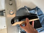
Spent the past few days taking things apart. Got most of the front clip off so I can have total access to the driver's side of the engine. The humidity here generates a lot of corrosion and surface rust. If you look closely at my cardboard template, you'll see a black line that would define a smaller piece (lower half). I had them cut one of those as well to possibly weld about 1 - 1/4" rear of the front mount edge. There is a tapped boss on the block that I could use to almost mirror image the lower tab and brace.
 
Brackets arrived from the vendor. Wow! Beautiful, and cut out exactly as drawn! Plan is to use the big one, but keep the other in reserve if additional bracing is needed. Hopefully get the bracket welded up this week, then move on to finalizing the turbo mount. Then I can tackle modifying the oil pan. Just got the front clip off and I have plenty of access to the engine. Now that I know this vendor can get the job done right, I need to have a special mounting plate cut for the turbo. It is the T4 style, and while there are plenty of plate available, they all have a rectangular cutout for the pipe. I need a circular hole, between 2 - 2 1/4". Haven't decided exactly on the size of pipe coming over (well, under, technically) from the exhaust manifold.

IMG_5140.jpg
 
Back from the welder. He had the ability to do the job much better than I could. All bolt holes line up and it bolts up with no binding. That’s a win. I thought it would only take a few minutes to fab a quick bracket to see how the turbo would mock up. That quick bracket revealed that it can’t fit up like the others I’m patterning this after. I had not accounted for two things: a 196 from a 800 model is clocked 15 degrees and has an intake that provides clearances that an IC 196 rotated back to a normal position, does not have. Plus the EGR hump on the underside doesn’t help. I can see a path forward but I’m done for today. It’s margarita time. Note that I had to remove my oil/coolant exchanger and filter mount. I now get to use that remote oil filter mount that I cast early on in this project! Just need to drill and tap for some 1/2" fittings.

Modified mount 1.jpg
Modified mount 2.jpg
 
Last edited:
Back
Top