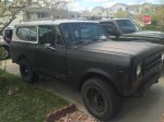
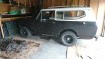
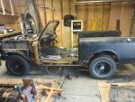
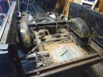
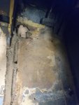
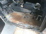
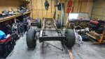
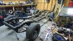
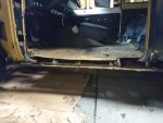
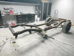
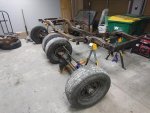
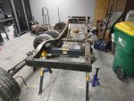
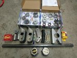
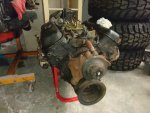
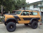
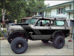
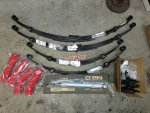
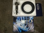
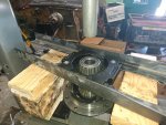
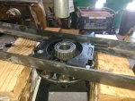
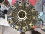
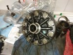
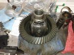
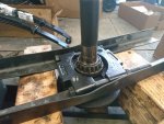
1979 International Scout II

Set up new axle shaft on press
 

Attachments

  • DSC_0146.jpg
    DSC_0146.jpg
    62.6 KB · Views: 570
I had made two dummy bearings for the carrier so I can easily take them off to adjust for side to side clearances in the housing. All I had on hand was some grinding stones with a 1/4 shaft and attached to my drill to grind down the inside of the bearing, just enough to slide on and off the carrier
 

Attachments

  • DSC_0175.jpg
    DSC_0175.jpg
    37.7 KB · Views: 572
Added dummy bearing to carrier and slid into housing to check for total side to side movement, so I can get a total shim count. This would give me a good idea of thickness I will need to add to the carrier.
 

Attachments

  • DSC_0155.jpg
    DSC_0155.jpg
    67.1 KB · Views: 572
I got roughly 0.0550 for my side to side movement. My first attempt I got roughly 0.0630 and I could not get the carrier back in the housing after adding shims. So a good point to make is make sure you pick a good flat surface to measure off of or your numbers will be off. I added a magnet, as you can see in the picture. With this being added I got a consistent value of 0.0550. I adjusted my shims and the carrier fit in snug with little light tapping of a dead blow to the bearing races.
 

Attachments

  • DSC_0182.jpg
    DSC_0182.jpg
    49.2 KB · Views: 569
I then measured the oil slinger thickness because I knew it would add to the height of the pinion but youll later see I forgot add to my shim calculations.
 

Attachments

  • DSC_0161.jpg
    DSC_0161.jpg
    46.8 KB · Views: 665
I also measured for the baffle for the same reason that I knew it would add to the total pinion height.
 

Attachments

  • DSC_0162.jpg
    DSC_0162.jpg
    54.5 KB · Views: 588
I then took my numbers (except for oil slinger), added them up and subtracted my added measurement of the baffle. This number gave me a starting point for my shim count under the inner pinion race.
 

Attachments

  • DSC_0163.jpg
    DSC_0163.jpg
    37.7 KB · Views: 569
Inserted pinion setup so I can measure for distance of side to side movement from pinion and ring contact point, and bearing seat position in housing. I must have deleted the picture, but I ended up with a 0.0170" movement.
 

Attachments

  • DSC_0167.jpg
    DSC_0167.jpg
    37.4 KB · Views: 570
I took the number I got and subtracted from the total shim count I got when I measured for total movement without pinion in place. The 0.0170 went on the ring side bearing and the 0.0380 went onto the opposite bearing.
 

Attachments

  • DSC_0184.jpg
    DSC_0184.jpg
    43.5 KB · Views: 557
I used the supplied marking grease and brush that came with my rebuild kit. I applied it to a few of the teeth on the drive and coast sides.
 

Attachments

  • DSC_0179.jpg
    DSC_0179.jpg
    51.7 KB · Views: 596
Before I started to rotating the ring, I made sure to tighten down bearing caps and pinon. I learned that not tightening the pinon, the pinion would shift/catch and move a little. I wanted to get the best markings I could, especially since this is my first attempt at rebuilding an axle. I made sure that I put the correct bearing caps back to their original locations and marked with paint to high light stamps as they were hard to see.
 

Attachments

  • collage-1495431264622.jpg
    collage-1495431264622.jpg
    38.3 KB · Views: 563
I added pressure to the top of the ring and rotated front to back, while maintaining pressure. I also kept my hand on the yoke neck to keep some resistance in the pinion as I rotated. As you can see I got a high marking on the coast side and a low marking on the drive side. So with a little searching I seen that I needed to adjust my pinion height. I needed to lower my shim count, which would have been a bigger adjustment if I added my measurement of the oil slinger.
 

Attachments

  • collage-1495431710148.jpg
    collage-1495431710148.jpg
    37.4 KB · Views: 578
Last edited:
Back
Top