Power Problems

Tracking, the rewire is going to have to wait, I woke up this morning to no heat and came home to a $300 repair bill. 
I am planning to take the body completely off the frame this summer to make some well over due repairs, maybe then.
Back to what brought me to post originally. From the pics posted does it look like the areas in question are wired properly??
Next, I pulled the yellow wire from the coil as you directed. I put the meter on 2000k resistance, and nothing, not change. I checked the volts just to make sure and it’s still getting 12.35volts.
The battery add on is proly going to have to wait for a couple weeks if the cost is more than half a bill. It looks like a complicated system, and I really need to get the truck proper before I go jumping into any new projects.
Thanks for the input, it really is appreciated.
 
2000k...that can't be the lowest setting on your meter? There should be a 2k or 20k at least. At any rate, the power feed from your ignition switch when properly resisted will also display a reduced voltage. I'd like you to trace that wire back as far as you can and tell me where it originates from. You could also trace out the green wire that is connected to the coil + and see where it originates. It should be coming from the lower small terminal of the starter-mounted solenoid.
 
Meter ranges from 2000k to 200. I tried on both with nothing on either. The green wire does go down to the starter. Traced that previously. I will let you know about the yellow tomorrow.
 
Okay. With a breaker points distributor, that wire running from the solenoid to the coil + is a resistor bypass feed. Its purpose is to provide full battery voltage to the coil only while the starter is being cranked. Once the engine lights off and the starter is released, the resistor feed from the ignition switch takes over. What I'm suspecting now is that you do not have a resisted feed to the coil. Rather it is being fed full voltage all the time, which is hard on both points and coils, leading to engine performance issues. As you trace this wire out, it would be good if you could examine the wire strands themselves too. Make note of whether they are normal copper or more like silver toaster wire.
 
Ok, traced the yellow cloth covered wire back to the firewall, bottom left connector, 1st position bottom left. This wire is silver in color.

The problem you describe with the constant full voltage, should I remove the the green wire and put the jumper in?
 
Last edited:
No. You need that bypass wire. Your description of the yellow wire sounds like it is the correct resistor wire and it appears to have the factory ring terminal at the coil end. I'm just puzzled by your reading of 12.x volts with the ignition on. It should be less than that. I was in error when I told you to take the resistance reading with the ignition on. It should measure approximately 1.8 ohm resistance with the key off and you need to put one probe at the beginning of the wire where it connects to the bulkhead connector and the other probe will go to the loose ring terminal removed from the coil. Sorry for not getting this right before. So please try that test again and see if you don't get a different result this time.
 
I kinda thought something didn't sound right so I did as you described just messing around to see what I would come up with, as I said befo I have only basic knowledge on the use of a multimeter. 2.1 ohms, with the meter set on 200. I will send you a pic tonight when I get home.
So would I be correct is saying that all the woring to this point is run correctly? Not good, but correct in how it is run.
 
Okay, that sounds a lot more guuder. Yes, I think the ignition related wiring is run correctly. Now I'd like you to measure the resistance across your coil terminals with the small gauge wires removed. We'll add that reading to the 2.1 of the wire to arrive at your total primary resistance.
 
That makes a total of 3.9 which is a bit high for a v8 with points. Ideally, we'd like to have a total between 3.2 to 3.4 ohms. Now when you traced out that insulated toaster wire, did you happen to notice an excess amount of wire basically doubled back over on itself several times? The length of this wire is what establishes the resistance, so it had to be considerably longer than the distance it needed to span. Now it is providing a bit more resistance than is required. That could be the result of corrosion on one or both sides of the bulkhead connector where that wire is attached. If the contacts are suspect, you should dress them to your best ability and re-measure the resistance of that wire. If there is no corrosion present and the contacts look perfect, you need to do something to reduce the resistance a bit. There are two options. One would be two shorten the wire and attach a new ring connector, provided there is enough excess length in the wire to do so. This is not an exact science. Snip a couple inches, measure the resistance...lather, rinse, repeat until a factor of @ 1.6 ohms is seen. The better option would be to do away with the resistor wire and run a length of regular automotive wire from the bulkhead to the coil. Then purchase a porcelain ballast resistor with a factor of 1.6 ohm. Take your multimeter to the store with you and measure before you buy. Mount it to your firewall near the bulkhead connector. Interrupt your new wire with the porcelain resistor. Done.
 
That wire is fairly short. 5feet at best. I will go for option 2 and buy a resistor. When I get it hooked up I will let ya know where it stands. Thanks
 
here is a good post on running dual batteries, thise is for a winch but it would work for a plow also.
http://forums.IHPartsAmerica.com/electrical-tech/2529-switchable-dual-batteries.html
Ron

Ron,
I was wondering if I would have to use all those switches etc... Or can the isolator be used by its self? I understand the voltage will be split between the two batteries, which results in a slower charge, other than that is it possible and what are the drawbacks??
Thanks
 
I'm frustrated.....
I shortened the cloth covered wire, it ended up being doubled over under the multitude of e-tape. I got it down to 3.3ohms thru the coil. The motor cranks real slow, but it did start.
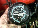
I have to keep my foot on the gas to keep it running until it warmed up. I made some minor adjustments to the idle speed screw. I don't have a tac so I'm just going by ear. It still seams a bit high once warm. I ran it for a good 1/2 hour, I took a vacumme reading once warm and it is steady around 17.5hg.
I took the rig down the road about half mile,came back everything appeared good, it was actually running good for the first time in years. Here is where it goes bad. Shut the truck down because I wanted to try and adjust the timming a little to see if I could get it to crank quicker, and there was no change either way I turned the dizzy, then I seen some smoke comming from down near the starter. The wire was so hot it started to melt the tape around the end of the cable.
The power wire is hot at both ends.
What am I missing???


A little more info. More is better right... I took a voltage reading 12 at the battery.
Key off 12 at the coil where the resisted wire is, nothing on the other side.
Key on 12 at both sides of coil.
 
Last edited:
Pic of the vaccume gage.
It cooled down and I got it started, I checked it with the timing with a light.
Pulled the vacumme off, and set it at 10bdtc, any lower and it would stall.
I know this is not the correct forum for this, but I figured a little extra info might help determine whats going on.
Thanks.
 

Attachments

  • Vaccume pres.jpg
    Vaccume pres.jpg
    46.4 KB · Views: 295
Last edited:
ron,
I was wondering if I would have to use all those switches etc... Or can the isolator be used by its self? I understand the voltage will be split between the two batteries, which results in a slower charge, other than that is it possible and what are the drawbacks??
Thanks
Well people have done it without but from what I have learned the isolator protects your batteries and alt. From damage. And the bat switch has come in very handy when working on my Scout and it also keeps the batts seprate so they both don't go dead. Meaning never needing a jump start, if done right. If it were my Scout with a winch or plow dual batts would be the way I would go.

Ron
 
I'm frustrated.....
I shortened the cloth covered wire, it ended up being doubled over under the multitude of e-tape. I got it down to 3.3ohms thru the coil. The motor cranks real slow, but it did start.
I have to keep my foot on the gas to keep it running until it warmed up. I made some minor adjustments to the idle speed screw. I don't have a tac so I'm just going by ear. It still seams a bit high once warm. I ran it for a good 1/2 hour, I took a vacumme reading once warm and it is steady around 17.5hg.
I took the rig down the road about half mile,came back everything appeared good, it was actually running good for the first time in years. Here is where it goes bad. Shut the truck down because I wanted to try and adjust the timming a little to see if I could get it to crank quicker, and there was no change either way I turned the dizzy, then I seen some smoke comming from down near the starter. The wire was so hot it started to melt the tape around the end of the cable.
The power wire is hot at both ends.
What am I missing???


A little more info. More is better right... I took a voltage reading 12 at the battery.
Key off 12 at the coil where the resisted wire is, nothing on the other side.
Key on 12 at both sides of coil.

A lot to digest here. I'll try and work through this as best I can. Good job on the resistance adjustment. I forget now what carb you have. Sounds like your choke isn't functioning. Proper choke function is necessary for easier cold starting. This needs to be examined. If the idle speed is too high, it will throw off your vacuum reading and also your timing adjustments. Timing is best adjusted on a warm engine at curb idle.
Are you sure you're getting 12v at the coil with the key off? This shouldn't be. It should be dead zero on both posts with the key off. You need to find out why and how the coil is being energized with key off. Constant energy there is bad. In fact, were I you, I'd disconnect that battery this instant until you can determine what's causing that constant hot. There should only be 12 volts through the green wire during starter cranking. Once the engine is running, the green wire goes dead and the resistor wire takes over providing roughly 8 or 9 volts. Key off - engine off...both wires should be dead.
 
Great just what I needed to hear. Lol. I will work on that this afternoon and get the rusults posted. Are there any other wires that need to be resisted inside the engine comp? I found 2 wires that have round connectors that are bolted together, it comes from the alt and goes into the the fuse panel. It starts out as a brown wire with white stripe and then it looks ltike the po spliced it with a red, then a green, the total lenght is like 8 or 9 feet. I looked in my toilet paper book and I can't find if it needs to be resisted anywhere.
 
There is one other resistor wire under the hood. It is a 24 gauge (tiny) brown with white stripe and runs from the #1 terminal of the alternator to the bhc. It should be one continuous wire run with a measured resistance between 10 to 50 ohms. Wires bolted together? That sounds sketchy. Are they under the hood or under the dash? Can you post a pic? Does the alternator gauge function on this rig?
 
I was a bit premature in agreeing with you a few days ago that your ignition/starter/alternator wiring was correct. Based on your smoking wires report, my recent review of the electrical schematic compared with a couple of your pics, and your description of wires bolted together...I have to re-nig on that assessment. My suspicion (and yours too) of these circuits should be back on the table. Obviously there is still some po virus rearing its ugly head. Every damn wire connected to that starter solenoid needs to be looked at and traced out to its termination. Same goes for the alternator.
 
Since I'll be outside and away from the pooter much of the day, here's your homework assignment. Focusing first on the starter solenoid gang of wires, we want the following in place:

a. One 4ga cable running from the battery + terminal directly to the large solenoid lug.
B. One 10ga wire (originally red with a fusible link) running from the large solenoid lug up to the bhc where it penetrates the firewall before terminating at the + lug of the alternator/ammeter gauge, known as circuit 14. Make note of any po splices or unions with other wires. It should be a solitary and continuous run other than the factory junction at the bhc.
C. One 16ga wire running from the large solenoid lug to the #2 alternator terminal, known as circuit 7. Make note of any splices/unions just as with #b above.
D. One 14ga wire running from the solenoid 's' lug up to the bhc, known as circuit 17 and originating from an 'I' terminal of the ignition switch. Again this should be free of splices/unions aside from the bhc. This wire completes the circuit to engage the solenoid plunger, which then allows the starter motor to turn.
E. One 16ga wire running from the solenoid 'r' lug to the coil + lug, known as circuit 16a. As before, check for splices/unions. Should be hot only during starter cranking. Must be dead 0 volts at all other key switch positions. All this wire does is momentarily bypass the resistor/ballast feed to the coil while the starter motor cranks. There should be no other wires connected to the solenoid aside from these five.

Now focusing on the alternator gang:

a. One 10ga wire secured to the 'b' or 'bat' lug with a nut, known as circuit 2. Should make a solitary and continuous run to the bhc, penetrate the firewall, and terminate at the - (negative) lug of the ammeter/alt gauge.
B. One 24ga resistor wire connected directly to alt terminal #1, known as circuit 1 (brown w/white stripe discussed two posts ago) and runs to the bhc where it penetrates the firewall and terminates at an 'I' terminal of the iggy switch. Has a measured resistance between 10 and 50 ohms. This as the 'exciter' wire, which prompts the internal voltage regulator inside the alternator to increase/decrease output based on current draw/load/drain etc.
C. Refer to #c of solenoid gang discussion above.

Finally focusing on the coil gang:

a. One 16/18ga black wire running from coil - (neg) to breaker points inside distributor.
B. Refer to #e of solenoid gang discussion above.
C. One 20ga resistor wire wrapped in cloth insulation, known as
circuit 16, originally 72 inches in length, with a measured resistance of 1.8 ohm. This wire should only display voltage when key switch is in on position. Should be stone cold dead when the key is in off or acc positions. To reiterate, the coil + lug has two wires connected. Both are called upon to supply voltage to the coil in differing situations, however neither should be energized when the key is switched to off or acc. Make it so, numba one!

This should keep you busy for awhile.
 
Last edited:
Got it. I was tracking the same thing. Today a got some electric parts cleaner and dielectric grrease, cleaned up those bhc's, put the connectors back together and nothing. I removed all the grease recleaned them with epc put them back together without grease nothing. It has been a long wet cold day here in pa. I will trace every wire and post findings in a few days.

The alt gage does work showes a positive charge, if I hade to guess I would say around 15 amps. The alt was pushing 15 amps befor.

I do believe that brown wire with stripe has been modified, the bolt is on ec side and the wire runs thru the bh in it's own modified hole. If I don't get a pic tonight I will post it along with all the other updates.

The carb is a an aftermarket Holley. (autoline c-7098). I am going to say it is similar to a 2300 with an electric choke. The choke does apear to work correctly, but I think it opens a bit fast, 2 or 3 mins and it is wo.
 
I'd not heard of these autoline remans before, so I had to edjumuhkate mysef on 'em a bit. Appears to be the oem design Holley 2300 with a 'lektrik choke. They look real purdy in the pics. Did they do a nice job on it in your estimation? Choke plate should start out almost completely closed when cold and be fully opened inside of 5 minutes. There should also be a fast idle cam that keeps the revs up around 1600, but gradually steps it down in @ 300 rpm increments until the choke is fully open.
Since you saw smoke escaping from the solenoid region, I'm not surprised you have nothing at the bhc. Your most recent failure could be right there at the solenoid which is upstream from the bhc. I bet when you make a close inspection you will find one or more crispi-fried wires there. I feel your pain on the cold, nasty weather, although it has been quite pleasant here in sw orygun the past few days. The po virus often leads to countless hours of hair pulling and teeth grinding. We'll eventually find and rectumfy the problems. If I could have my boots on your soil with diagrams in hand this process would be a bit faster. Small snapshots with back and forth he said/he said is kinda slow and plodding, but its the best we can do.
 
I will be busy at work for the next couple days, I have a big inspection and will be workin some late uns.
The carb seams to be doing ok, when I first put it on it ran gud for bout 2 weeks, I had someone look the rig and they made some adjustments, but it has never been "right", but I have come to the conclusion that there were proly other issues and the carb should have beenleft alone, say la vee. There is no fast idle cam an this carb. I do have 2 old 2100's that I might be able to rob some parts from, but I will get you some gud pics of what I got going on for we get the cart rollin.
Good night.
 
I find it hard to believe that there is no fast idle provision on your carb. That's like a reeses peanut butter cup without the chocolate. A carb choke system that doesn't increase engine speed during warmup is practically worthless. One should not have to feather the throttle or carefully position a brick paver on the accel pedal in order to keep the engine running. You'll have to prove it to me with some good carb pics...time permitting of course. I think it exists and simply needs adjustment in order to actuate properly. The motorcraft 2100 carbs you mentioned May appear somewhat similar at first blush, but there really won't be anything of consequence that can be transferred over to the Holley. Have fun at work.
 
Last edited:
Back
Top