152 rebuild

Started tearing everything apart tonight. No real issues so far. I did have some questions for you guys though. First, looking at the transmission side of the bellhousing (is that the right term), it looks like the holes on the bottom on each side are bigger than the others. The manuals speaks of sleeves or something like that, and I think I can see something in their picture. Are there supposed to be sleeves in those bottom holes? If so, I don't have any. I'm certain they didn't fall out when I pulled it apart.

Next, what should I look for to decide if my throwout bearing is good to go? It has slop in it (side to side) but I'm not sure if that's normal. Also, some indentations where the fork presses. Not sure if that's okay either. That whole slave cylinder setup is kind of a sloppy operation with the angles and range...

Thanks for the help.

Oh, one other question. Is it necessary to keep track of how the clutch and flywheel are oriented, for balance reasons? I already removed the clutch, so hopefully the answer is no.
 
Last edited:
started tearing everything apart tonight. No real issues so far. I did have some questions for you guys though. First, looking at the transmission side of the bellhousing (is that the right term), it looks like the holes on the bottom on each side are bigger than the others. The manuals speaks of sleeves or something like that, and I think I can see something in their picture. Are there supposed to be sleeves in those bottom holes? If so, I don't have any. I'm certain they didn't fall out when I pulled it apart.

Next, what should I look for to decide if my throwout bearing is good to go? It has slop in it (side to side) but I'm not sure if that's normal. Also, some indentations where the fork presses. Not sure if that's okay either. That whole slave cylinder setup is kind of a sloppy operation with the angles and range...

Thanks for the help.

Oh, one other question. Is it necessary to keep track of how the clutch and flywheel are oriented, for balance reasons? I already removed the clutch, so hopefully the answer is no.

The flywheel will go back on the crank only one way due to the dowel location. Not necessary to keep the clutch cover in the original position, but it's always standard practice to do so if you are going to re-use.

The clutch throwout fork and throwout bearing sleeve should be reworked or swapped for a reconditioned set:

http://www.forums.IHPartsAmerica.com/new-products-IH-only/1862-Scout-80-clutch-components.html

Additional reconditioned clutch fork sets are on their way to ihon in Loomis.

Always replace the throwout bearing and pilot bearing when an engine or tranny is out...standard practice if the age/operational hours of those parts are unknown!

The two lower holes ya mention in the lower/rear of the engine bell should contain alignment dowels...very important! Those align the centerline of the transmission input shaft with the centerline of the crankshaft. The dowels May be in the clutch bell or in the engine, or one of each. Doesn't matter which part they stay with as long as they are present. You will also find a similar dowel in the block's deck at each end for cylinder head alignment. And new replacement dowels are in stock now at ihon.
 
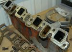
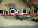
Ripped most of the rest of the easy stuff off tonight. Check out the picture of the intake manifold. The one coolant opening is solidly plugged with something resembling concrete. This can't be right, right? There's an opening on the head there, so I'm kind of confused why someone would do this.
 

Attachments

  • intake.jpg
    intake.jpg
    59.6 KB · Views: 883
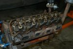
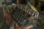
Here are some misc pictures for the record. I pulled the plugs out and was turning the engine over and over trying to understand the timing of the valves. I put the distributor back in the way I thought it was originally, but heck if I can get it to come around to where the #1 plug wire is when I think it should according to the valves.

Hypothetically speaking :rolleyes5:, how would a person go about installing the distributor properly if he just showed up cold and had to figure it out with no information?
 

Attachments

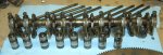
  • rockers.jpg
    rockers.jpg
    59.1 KB · Views: 428
  • rods.jpg
    rods.jpg
    60.4 KB · Views: 438
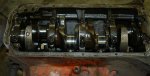
  • crank_in.jpg
    crank_in.jpg
    52.4 KB · Views: 419
Here's a shot of the throwout bearing and fork. A friend came by tonight and he's certain it's shot based on the amount of slop in it. Is the bearing a press fit onto the collar?

I'm leaking a lot of oil from the front of the trans. I can access the seal from here, right? Is there a front bearing I can access from the front also?
 

Attachments

  • throwout.jpg
    throwout.jpg
    39.6 KB · Views: 838
here are some misc pictures for the record. I pulled the plugs out and was turning the engine over and over trying to understand the timing of the valves. I put the distributor back in the way I thought it was originally, but heck if I can get it to come around to where the #1 plug wire is when I think it should according to the valves.

Hypothetically speaking :rolleyes5:, how would a person go about installing the distributor properly if he just showed up cold and had to figure it out with no information?

There's a thread here somewhere describing the "stabbing" procedure for distributors in these vehicles. To find the #1's tdc, put a soft rod or dowel or whatever in the plug hole and "feel out" when it tops out. I think intake will be closing a little after bdc, so start turning more slowly after you witness that valve event.

You also have to account for the fact that the teeth in this gear are cut at an angle, which means you must "offset" your ideal timing position. It's because of this that a lot of people stab it straight-down and get it a tooth or two off as it follows the angle, enough to where adjusting the body won't make up for timing.

So don't forget to look at those teeth before you install it and remind yourself to "back up" and allow the teeth to bring it into position. You also have to make sure there is some kind of brass(?) bushing seated correctly down below to bear the gear-end of the distributor shaft, too. I highly recommend getting more information from the thread I can't seem to find.
 
Last edited:
ripped most of the rest of the easy stuff off tonight. Check out the picture of the intake manifold. The one coolant opening is solidly plugged with something resembling concrete. This can't be right, right? There's an opening on the head there, so I'm kind of confused why someone would do this.

That is the originally-engineered exhaust heat crossover passage. Since your engine is a very early model, I would have expected to see that passage "open" but have a blocker segment incorporated into the intake gasket.

Exhaust heat was not used nor needed on the 152 engine in the Scout 80, but was most likely used on that engine when used inna tractor, bailer, or as a pump engine...all common uses.

This engine was manufactured in this manner, that is not a po virus deal! Some manifolds were "plugged" with some type of epoxy material back in the day...later aluminum manifolds simply had the runner left in the mold/casting, but the actual passage was blocked during the foundry process.

This shot is a very early 152 intake that has a functional exhaust heat crossover. I installed it on the engine in the pics I posted swinging from the hoist (the refurbished motor). This is the only one I've personally had my mitts on, but I've played with many just like yours...I have three of 'em now!
 

Attachments

  • VERY EARLY 152 Intake.jpg
    VERY EARLY 152 Intake.jpg
    122.2 KB · Views: 845
here are some misc pictures for the record. I pulled the plugs out and was turning the engine over and over trying to understand the timing of the valves. I put the distributor back in the way I thought it was originally, but heck if I can get it to come around to where the #1 plug wire is when I think it should according to the valves.

Hypothetically speaking :rolleyes5:, how would a person go about installing the distributor properly if he just showed up cold and had to figure it out with no information?

Simple version for a 152/196:

1) align timing Mark on crank hub with zero tick Mark on timing quadrant, cylinder #1 must be at tdc on the compression stroke, not the exhaust stroke!!

2) with cap removed and the #1 terminal on the cap marked on the distributor body with a marker, align the tip of the rotor with the Mark on the distributor body.

3) rotate the distributor shaft/gear slight ahead of where the Mark on the body is to allow for the helix angle of the drive gear...as you face the engine, the vacuum advance can should be facing you and on the right side for proper rotational clearance.

4) stab it in, aligning the oil pump drive tang as it goes in.

You can make any of the four cable sockets on the cap to be #1 when you align the rotor. Just make that hole #1 cylinder and then go around the cap clockwise and install the plug cables in the firing order pattern: 1, 3, 4, 2.
 
here's a shot of the throwout bearing and fork. A friend came by tonight and he's certain it's shot based on the amount of slop in it. Is the bearing a press fit onto the collar?

I'm leaking a lot of oil from the front of the trans. I can access the seal from here, right? Is there a front bearing I can access from the front also?

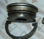
The throwout bearing is a very "light" press fit, the collar May be driven out of the bearing with a light hammer and drift.

The collar must be "renewed" along with the throwout fork, see those two heavy wear points??? Those will be "moved" when ya install a freshened collar on a reconditioned fork so there is only a slight running clearance between the fork tips and the collar groove. That wear is why you cannot use over one-half of your slave cylinder travel to release the pressure plate! And you May also see that the clutch throwout arms have actually eaten into the fork itself. Then a replacement throwout bearing is tapped onto the collar.

You can access the seal and gasket on the front nose of the tranny, but do not pull out on the input shaft while the bearing retainer is removed!!!!!
 
The manual tells me to use a ridge reamer on the the cylinder prior to removing the pistons. Is this a necessary step? I don't have a ridge reamer of course...
 
the manual tells me to use a ridge reamer on the the cylinder prior to removing the pistons. Is this a necessary step? I don't have a ridge reamer of course...

Feel along the top of each cylinder where the top ring's travel ends - is there a definite ridge? I would think that unless this ridge is large enough to feel, it won't provide serious interference.

If you can take the pistons out, take them out - just don't forget to find a way to determine wether or not a ridge exists. A precision straightedge or small rule plus a good set of tiny feeler gauges might help here. This would be something I'd do when checking cylinders for elliptical wear and overall wear.
 
Yeah, there's a ridge. It doesn't seem huge, but it's there. The pistons won't come out easily. Should I go find a reamer, or will they come out the back way for me if I get the crank out?

Also, any advice on getting the harmonic balancer off? I borrowed a puller from the parts store, but it's not big enough to span all the way across. I'm assuming there's another kind of puller that will do it.

Here's a pic of my carbon laden pistons not coming out. Is this amount of carbon extreme, or pretty typical for an old motor like this?
 

Attachments

  • piston_carbon.jpg
    piston_carbon.jpg
    31.6 KB · Views: 794
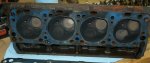
Here's a pic of the bottom side of the head. How do the valves look to you guys? I think my plan is to take the head to a local shop and have them do the checkout/rebuild. I'll have them dip the block also.
 

Attachments

  • cylinder_head_bottom.jpg
    cylinder_head_bottom.jpg
    43.3 KB · Views: 843
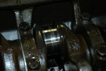
I think I found my first serious casualty. Check out the crank where the #3 rod was removed. It's seriously scored. The rod was attached with different bolts than the others, though it seemed tight. Someone was messing with it. Can I recover from this, or do I need a new crank?
 

Attachments

  • damaged_crank.jpg
    damaged_crank.jpg
    50.9 KB · Views: 796
yeah, there's a ridge. It doesn't seem huge, but it's there. The pistons won't come out easily. Should I go find a reamer, or will they come out the back way for me if I get the crank out?

Also, any advice on getting the harmonic balancer off? I borrowed a puller from the parts store, but it's not big enough to span all the way across. I'm assuming there's another kind of puller that will do it.

Here's a pic of my carbon laden pistons not coming out. Is this amount of carbon extreme, or pretty typical for an old motor like this?

I would recommend finding a reamer, but I've never hands-on done any of this - I just know that you might as well do it yourself instead of paying someone, if you can get your hands on a reamer and it's easy enough to use. I can't say anything about the balancer for lack of experience.

As far as the amount of carbon - that looks extreme, but I guess any old motor I've seen that has experienced heavy use (maybe abuse..?) looks like a lesser degree of your own situation. It's to be expected, I suppose, if you're intending on investing in a rebuild.

here's a pic of the bottom side of the head. How do the valves look to you guys? I think my plan is to take the head to a local shop and have them do the checkout/rebuild. I'll have them dip the block also.

I highly recommend doing as much research as possible (asking around with locals, doing online searches, finding reviews, etc) for your decision regarding a machine shop. I would hate to hear a story of less-than-expected outcome when your stuff gets finished.
 
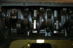
A few more pictures. One of the whole crank as it stands, another of the removed rockers.
 

Attachments

  • crank_in2.jpg
    crank_in2.jpg
    58.5 KB · Views: 454
  • rockers_out.jpg
    rockers_out.jpg
    46.5 KB · Views: 421
I think I found my first serious casualty. Check out the crank where the #3 rod was removed. It's seriously scored. The rod was attached with different bolts than the others, though it seemed tight. Someone was messing with it. Can I recover from this, or do I need a new crank?

Again up to the machine shop, I suppose, and what they can do for you concerning your level of damage. Due to the construction of these cranks, you should be able to have them ground down to a pretty deep undersized bearing - that would be your limit as far as repair can go. Not to mention that would likely promote healthy cost.

Depending on the depth of the gouging and the condition of the other journals, though, you might have what is considered "reman"-able material.

a few more pictures. One of the whole crank as it stands, another of the removed rockers.

Looks like you have the preferred rocker setup. Depending on the condition of your pushrod and valve contact points, as well as the shaft's exterior, this might be doing okay. Pretty sure I read that a "verified good" setup is available from ihon if necessary.

Also - I think you can buy replacement plugs for the rocker shaft, so it might be a good time to find a shotgun cleaning brush to sterilize the inside of that shaft. Something I should have done to my 304 ages ago, just as a preventative maintenance sorta thing.
 
Don't worry about what you are finding. While not desired the cylinder wear and rod journal damage is an easy detail to fix. The old bearing shells hav a number stamped into them telling the under size if not then it is still standard and bearings are availible in -.010 -.020 etc to -.040. No issue with streagnth at all. Iirc 100 bucks to gring a 4 banger .010 under rods and mains. First go guy a 2-3" micrometer so you can measure the crank to determine if you need to go under size.

You will probably need to wack the rod with a soft face mallet to get them past the ridge and accumulation of carbon. Just rotate the crankout of the way. Some times a wood block helps to persuade
 
A few more questions: the manual talked a bunch about the special bolts that hold down the rocker arms... Something about a nylon bead or something like that. They looked like normal bolts to me, though the manual said that in no circumstances should regular bolts be used. Anyone know about this?

The other thought I had was whether one of you ihon affiliated guys would be interested in doing the head rebuild? I was thinking of taking it someplace local, but shipping it really isn't a big deal, and you guys (michael, Robert) really understand the IH stuff.

Should a competent local shop be able to check out the crank for me?

Last question is how I should proceed with the cylinders. I'll have the block checked out, but if it needs to be bored out a little, what's the best approach, bore it over a little and get oversized rings for the same piston, or bore enough over to get bigger pistons? Are bigger pistons attainable?

Thanks.
 
a few more questions: the manual talked a bunch about the special bolts that hold down the rocker arms... Something about a nylon bead or something like that. They looked like normal bolts to me, though the manual said that in no circumstances should regular bolts be used. Anyone know about this?

The other thought I had was whether one of you ihon affiliated guys would be interested in doing the head rebuild? I was thinking of taking it someplace local, but shipping it really isn't a big deal, and you guys (michael, Robert) really understand the IH stuff.

Should a competent local shop be able to check out the crank for me?

Last question is how I should proceed with the cylinders. I'll have the block checked out, but if it needs to be bored out a little, what's the best approach, bore it over a little and get oversized rings for the same piston, or bore enough over to get bigger pistons? Are bigger pistons attainable?

Thanks.

The IH admonition regarding the "special bolts " for the rocker shaft is fine. But certainly not needed! I use replacement bolts in either grade 5 or grade 8 weekly...we also have several "sets" of used bolt...those bolts are not a "high stress area since they are clamping aluminum towers. The threads of the bolts get treated with a sealant when ready to re-install as some of them thread directly into the intake ports. The bolts do need hardened washers under they heads though, re-use the oem if they are present.

My advice would be to have one machine shop do all your work as a package, that makes them responsible for the work. Just the cost of shopping a head is unbearable in my world! Doing a valve/head build is not something any different than doing any other head as long as the machinist pays attention to detail, most especially setting up the installed valve height on the IH heads due to the non-adjustability of the hydraulic valve actuation system.

That shop will measure the bores and determine if a bore job is needed. If so...all cylinders are then bored to the oversize tolerance based on the actual size of each of the matching replacement pistons, then the appropriate oversize rings are fitted after verifying the end gap of each ring set in it's dedicated bore and "adjusting" the gap if needed by hand filing. That is called attention to detail and separates an "ok" engine build form the "outstanding" engine build!

The same machine shop will determine the condition of the crank and then either polish it if doable, or regrind it and supply the correct size rod and main bearings or tell you which size bearings to order for making the final assembly.

The same shop will "clean" the parts, and install the soft plugs if desired. Same for installing the cam bearings, that operation is beyond the doability of most diy'rs and requires special tooling setup and much attention to detail.

Once the engine has gone through the machine shop cleaning phase, then the hand work really begins regarding cleaning all passages and threads to remove any possible microsopic contamination. Any yahoo can assemble (or attempt to do so) an engine short block...it's attention to cleanliness and detail that makes the work successful.
 
I called a local machine shop that I bought a 350 Chevy from once a while back. When I told him what I had he seemed totally familiar with it (IH 152). My plan is to strip the block the rest of the way and bring him that plus the head and the crank next week. I'll probably go ahead and bring him the cam and rod/pistons too so he can see the whole situation and help me figure out what to do.

The pistons came out easily with just a little persuasion from a rubber mallet and piece of wood. I pulled the cam and to the eye it looks to be in fine shape. I used some sort of gear puller to get the harmonic balancer off, borrowed from the parts store.

At this point all I have left is the crank. I'm stuck at the main bearing since I don't have the right puller. I'll go looking for that tomorrow.

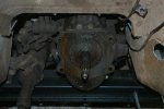
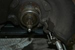
I decided to start tearing into the front of the trans. I pulled the bellhousing first, even though I'm not sure it's necessary. I wanted to get a look behind it, plus it'll be fun to clean it up and put on a coat of paint.

If this spot is leaking, where would it be coming out, at the case or up the shaft and out the end? I'm not sure what to expect when I pull the little cover off.
 

Attachments

  • trans_front.jpg
    trans_front.jpg
    51.7 KB · Views: 854
Here's a pic of my throwout bearing assembly. It's go a decent divot out of it where the fork contacts it. The bearing part itself is really sloppy, it must be shot. Does ihon sell these as an assembly, or bearing and collar apart?
 

Attachments

  • throwout_out.jpg
    throwout_out.jpg
    50.2 KB · Views: 856
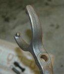
I bought this fork off e-bay a while back, figuring I'd need one some day. It's got a little bit of a flat spot on the prongs, but not much. Does it look decent as far as you can tell from a picture? There's a small amount of play on the bolt, but not much.
 

Attachments

  • fork_new.jpg
    fork_new.jpg
    22.8 KB · Views: 855
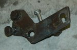
Check out this slave cylinder mounting bracket. Is this even close to how it's supposed to be? It has been working for me, but it looks like a mess, and I'm not sure my geometry is as it should be.
 

Attachments

  • slave_cyl_mount.jpg
    slave_cyl_mount.jpg
    51 KB · Views: 863
I called a local machine shop that I bought a 350 Chevy from once a while back. When I told him what I had he seemed totally familiar with it (IH 152). My plan is to strip the block the rest of the way and bring him that plus the head and the crank next week. I'll probably go ahead and bring him the cam and rod/pistons too so he can see the whole situation and help me figure out what to do.

The pistons came out easily with just a little persuasion from a rubber mallet and piece of wood. I pulled the cam and to the eye it looks to be in fine shape. I used some sort of gear puller to get the harmonic balancer off, borrowed from the parts store.

At this point all I have left is the crank. I'm stuck at the main bearing since I don't have the right puller. I'll go looking for that tomorrow.

I decided to start tearing into the front of the trans. I pulled the bellhousing first, even though I'm not sure it's necessary. I wanted to get a look behind it, plus it'll be fun to clean it up and put on a coat of paint.

If this spot is leaking, where would it be coming out, at the case or up the shaft and out the end? I'm not sure what to expect when I pull the little cover off.

Take every part that has a "spec" to the machinist so he can measure everything and determine what needs to be done. That way the machine shop is responsible for everything!

Your 152 does not use a "harmonic balancer...it uses a crankshaft "hub" that was individually matched to your engine at the time of manufacture, same as the flywheel. That hub has been drilled for balance factor for the engine rotating assembly as it currently is. Your machinist will advise at what point the rotating assembly needs to be "re-balanced" if a bore job is needed. But in my world, even if you just end up ringing the motor, a full balance job is well worth the money and will greatly improve upon the "factory" balance work.

In your picture, we're looking at the input shaft and input shaft bearing retainer. There is a gasket behind the retainer along with a seal. All soft goods needed for "sealing" the transmission are contained in a gasket set for that trans...some parts in the kit are not used in your version of a t-90.

The transfer case is addressed as a separate item...it also has a dedicated gasket/seal kit for it that contains many parts that are not used on the s80 version of the d18 case but that is the way the kit is sold...it also fits a d20.
 
Back
Top