Torqueflite 727 Guapo

Michael Mayben

IHPA Tech Moderator - Retired & No Longer Online
Let's use this thread for anything related to the chrysler-supply torqueflite 727 tranny as used in both "d" model fullsize stuff and Scout II.
 
First off, we need to be able to identify which tf 727 basic unit we are dealing with. There were three main variations produced, one for all chrysler engine apps, one for amc engines, and of course, the unit used in ihc beginning sometime in the m/y 1972 production run of various platforms.

The first pic shows the amc variation...notice the full "circle" bellhousing, with the starter mounted on the passenger side. Starter location is the most obvious point of identification.

The second pic shows a chrysler engine application, again, full circle bell, but the starter is on the driver side.

Third pic shows a typical ihc tf 727, starter on the passenger side...but bolted to the block...not the transmission bell. And...notice the sheet metal "filler" piece mounted to the bottom of the "cutaway" bell, allowing for attachment of the flex plate/torque converter dust cover.

All tf 727 variations will always have a unique identifying number set stamped (not cast) into the pan rail on the driver side, just below the shift lever location...that is usually a "partial" serial number (earlier vehicles), or vin (later vehicles). That will tie the particular transmission case to it's original oem installation.

The 727 shown in the last pic is a very early tf 727 chrysler app (late 1966), notice the numbers stamped into the pan rail, lower left corner of the shot.
 

Attachments

  • Chrysler 727 Bell.jpg
    Chrysler 727 Bell.jpg
    84 KB · Views: 8,922
  • IHC 727 Bell.jpg
    IHC 727 Bell.jpg
    100.6 KB · Views: 4,410
  • Chrysler 727 Serial.jpg
    Chrysler 727 Serial.jpg
    115.4 KB · Views: 4,126
  • AMC TF 727 Bell.jpg
    AMC TF 727 Bell.jpg
    53.3 KB · Views: 8,380
For a the lazy

attachment.php


attachment.php


attachment.php


attachment.php
 

Attachments

  • AMCTF727Bell.jpg
    AMCTF727Bell.jpg
    70.3 KB · Views: 17,152
  • Chrysler727Bell.jpg
    Chrysler727Bell.jpg
    107.7 KB · Views: 15,559
  • IHC727Bell.jpg
    IHC727Bell.jpg
    130.6 KB · Views: 17,842
  • Chrysler727Serial.jpg
    Chrysler727Serial.jpg
    149.6 KB · Views: 14,427
Last edited:
Thanks for labeling the pics Craig! Wish I knew how to do that stuff! It's all I can do ta just take tha pics!
 
Any transmission (manual or auto), transfer case, or axle system must be vented to the atmosphere in some manner.

Vehicles which see street use only can get by with whatever vent system the oem/component manufacturer provided. But in the case of off-road use, those vent systems are entirely inadequate.

In off-road use, the vehicle May see deep water, deep mud (or both at the same time), deep snow, sand, etc. Even worse is when the rig becomes stuck or submerged in any/all the above! At that point, the external contamination can move right through the oem-design vent systems and become entrained inside the power transmission component where it will soon wreak havoc unless a complete removal is performed asap.

Kinda makes sense in those cases to not allow the crap ta get inside in the first place don't it??

Let's look at how we can upgrade the tf 727 tranny vent system, and also it's companion tailshaft/transfer case adapter system inna Scout II "married" 4x4 app.

First we'll look at the 727 vent system...
 
Ihc made the switch to the tf 727 tranny from the borg warner slushbox for all light line applications sometime in mid-1972 production. Those trannys used what I call an "early" design transmission case vent.

The vent is located on the upper portion of the front pump housing. It consists of a machined passage in the pump casting, which is covered with a sheet metal "baffle" visible from the outside once the torque converter is removed.

Internally, there is a similar baffle mounted which covers the actual vent penetration.

This vent system will allow water inside the tranny if the rig is stalled in a deep water crossing. So we're gonna eliminate it and add a new vent to the tranny case itself, located at the highest point, with a tube run to an even higher location on the vehicle. In order to do a vent relocation the transmission must be torn down, so it's best to do this when accompanied by a complete rebuild.

First the pump is removed from the case, and the oem baffles are also removed and added to your scrap pile of useful bits of sheet metal for some other project.

Next, from the inside of the pump casting, the oem vent hole is drilled and tapped to 1/8" npt, and a brass internal wrenching 1/8" npt plug is inserted permanently. This process seals the oem vent forever as if it never existed.
 

Attachments

  • Early Vent Baffle External.jpg
    Early Vent Baffle External.jpg
    82.2 KB · Views: 2,180
  • Early Case Vent Baffle Inside.jpg
    Early Case Vent Baffle Inside.jpg
    100.7 KB · Views: 2,400
  • Tap OEM Pump Vent For Plug.jpg
    Tap OEM Pump Vent For Plug.jpg
    106.5 KB · Views: 3,062
Here's shot of the completed pump, showing the brass plug installed with appropriate thread sealant.
 

Attachments

  • Early OEM Vent Plugged.jpg
    Early OEM Vent Plugged.jpg
    98.1 KB · Views: 12,633
Sometime during my 1973 production, chrysler changed the vent design , along with the pump housing.

The re-designed vent system consists of a plastic vent "module" which is mounted in a large boss machined into the pump body from the inside and retained with a drive rivet. Only the vent hole is visible from the outside and no sheet metal baffle was used

this vent system is by far the most common used in ihc applications, both fullsize and sii. To eliminate it, a similar but different process is employed.

This pic shows a chrysler motor home tranny that I resurrected and converted to a married transfer case output shaft/tailhousing for installing a 440 dodge motor in a sii mud/sand drag rig. I gayrondamteeya the completed tranny don't look like this now! This is typical of a tranny that's been left out in the weather for some time (can we say boneyard?). This unit was heavily dosed with rain water that had entered through that vent hole and the dipstick tube.
 

Attachments

  • OEM Case Vent On Pump.jpg
    OEM Case Vent On Pump.jpg
    111.9 KB · Views: 12,318
Last edited:
Here's the actual plastic vent unit installed on the rear of the pump housing.
 

Attachments

  • Plastic Vent Assembly Internal.jpg
    Plastic Vent Assembly Internal.jpg
    111.6 KB · Views: 13,134
Here again, we're gonna plug off the oem vent hole, but we're gonna do this from the outside of the pump body, that is a much easier drill/tap process than performing the mod in the early vent system.

Simply use the appropriate drill bit to enlarge the existing hole and drill straight through the plastic baffle, no need to control the depth of the drill bit unless ya want to with a stop collar.

Then tap to 1/8" npt and install the brass plug and set it. In this case, I use hylomar (shop staple) for the thread sealant.

This completes the blocking of the oem vent for both types of systems.

Next up we'll add the actual relocated vent to the tranny case itself.
 

Attachments

  • Drill_Tap_Plug OEM Vent Hole.jpg
    Drill_Tap_Plug OEM Vent Hole.jpg
    121.2 KB · Views: 11,912
Now let's install the new case vent at the highest point on the tranny that is on the "wet" side of the pump.

The approximate location (not super-critical) is 1" to the driver side of the case mold parting line, and on the "sloped" portion of the case about 1" to the rear of the internal machined surface where the cast iron pump body seats against it's gasket. The case is very thin at that point so the hole must be drilled with the correct tap drill and must be absolutely perpendicular to the case casting itself.

Once the hole is drilled, then tap with a 1/8" npt tap, clean the threads and install a 1/8" nptx5/16" right angle hose barb. Be sure to seal the threads with the appropriate thread sealant and align the barb parallel with the case mold parting line and pointed towards the front of the case.

The large, 1" diameter hole in this bellhousing is for engine timing Mark access. This tranny is a motor home unit, which was bolted behind the hd/industrial/motor home dodge 440 engine. When those motors/chassis were used by the various coach manufacturers, the original timing marks on the timing case and the harmonic balancer were not visible/accessible, so chrysler put the timing marks on the tranny bellhousing and the flex plate so they were easily seen when the doghouse was removed.

Sorry for the suk quality of one of the pics, I'd never actually looked at those shots until today.
 

Attachments

  • Tap Case Vent Hole.jpg
    Tap Case Vent Hole.jpg
    112.2 KB · Views: 2,384
  • Relocated Vent Internal View.jpg
    Relocated Vent Internal View.jpg
    43 KB · Views: 1,770
Last edited:
Here's a shot of the brass vent nipple installed.

No matter which year model 727 tranny is being modified, the case vent goes in the same position. Only the pump plug scenario is different.

Once the tranny is re-installed, then connect a length of 5/16" fuel-rated flex hose to the barb and run to a location in the engine bay, where it should end in an "air gap" loop and run into some form of catch can to prevent tranny fluid from spilling on the ground (or hot engine) during extreme angle operation (aka upside down/on yore side). We're gonna run the new transfer case adapter vent to the same location later on, along with a positive vent for the d20/d300 transfer case itself.
 

Attachments

  • Relocated Case Vent Installed.jpg
    Relocated Case Vent Installed.jpg
    141.2 KB · Views: 12,114
Ok...the Binder Bee 2008 is now history, I can get back on this thread and finish up the vent relocation.

On the passenger side of the tail housing/transfer case adapter there is a vent hole approximately 3/16" in diameter. This hole is located about two-thirds of the way up on the side of the case, just in front of where the transfer case meets the adapter flange. Absolute worst place to put a vent...right where it catches all the mud/goop/water/etc. That the rig sees in trail use!

We're gonna fix that!! But first, the tailshaft housing must be removed from the tranny! There is no way to do this mod with it installed in the vehicle, not proper access, visibility, etc. And ya can't keep the debris out of the hole when preparing.

This vent serves to equalize internal pressures generated from heat/cooling of the drive train components with atmospheric pressure, and prevents oil seal "blowout". Behind the transmission input gear on a 727 tranny there are two seals and a precision-ground spacer upon which the seal lips ride. The drive gear retaining nut locks the drive gear to the output spline, the inner bearing race, and sets the position of the drive gear with the transfer case input gear so that maximum gear dog engagement is achieved.

One seal lip points towards the tranny to keep working fluid inside the case. The other seal lip points toward the transfer case to achieve lube retention. Pretty simple...there is a space of approximately 3/8" of an inch between the two seals, that is where the tail housing vent hole penetrates.

The pic is kinda crummy but it does get the point across. The tailhousing on the left is for a 727 as used inna 2x4 Scout II, or a fullsize pickup/Travelall either 2x4 or 4x4. So this mod pertains only to a Scout II with a married transfer case.
 

Attachments

  • D20 tailhousing bearing_seals_spacer.jpg
    D20 tailhousing bearing_seals_spacer.jpg
    438.2 KB · Views: 12,453
The drilling/enlargement of the existing hole is a somewhat tedious operation. We're gonna drill it at exactly the same angle as the hole that is already in the case, but only to one-half the depth of the original hole! This is critical!!!

If ya don't drill the hole exactly on the same centerline, then you will drill through the case itself and break through to the outside!

I forgot to add the correct pic, lemme try again!
 

Attachments

  • Vent Hole Drilled and Tapped.jpg
    Vent Hole Drilled and Tapped.jpg
    361.6 KB · Views: 12,015
Last edited:
Once the hole is drilled to the proper size for the 1/8"npt thread on the barb fitting, it must be cleaned of all chips. And the bearing itself must be cleaned also without removing it from the case. Now is the time to replace both seals also!

Proper inspection calls for removal of the bearing from the case which can be a real pain...the case should be heated in an oven for about an hour at 400*f and the bearing will fall out (once the retaining ring is removed which is a major pita!). Replacing the bearing calls for heating the case again, while chilling the bearing in a freezer for about two hours.

Next seal the threads with whatever you used on the front pump vent plug (I prefer hylomar) and tighten the new vent hose barb.

Once the entire powertrain is re-installed, run vent hoses from both vents to a common point as high in the engine bay as possible. Preferred method is to run 'em into a "catch can" if possible so that any vapor or liquid which might exit the vents cannot spill onto a hot exhaust. And the hoses should incorporate a "loop" to serve as an air gap, something along the lines of what is used when plumbing a dishwasher into the disposal in the kitchen sink!
 

Attachments

  • Hose Barb Vent.jpg
    Hose Barb Vent.jpg
    367.6 KB · Views: 11,981
Now we're gonna jaw about "the bearing"!!

This issue pertains only to a Scout II 727 tranny witha married transfer case.

The pic shows three different variations of a 727 tailhousing (and this doesn't even begin to cover all the variations that were produced!!).

On the left is a dodge 440 motorhome tranny, this would be near identical to the same item found in some ihc motorhome chassis. Next to the hemi version of the 727, the motorhome unit was the most rugged variation chrysler produced and was the same unit found in medium duty dodge trucks.

The center unit is what is found on ihc 2x4 Scout II, and all fullsize 2x4 and 4x4 vehicles (except motorhome chassis).

The tailhousing on the right is for a Scout II married transfer case...that is the unit previously discussed regarding the vent relocation project.

The dodge and the ihc output shaft ball bearings are dimensionally identical. However, the dodge unit is a "9 ball" bearing (higher load capacity), while the ihc bearing (that tranny is from a t'all)is a "8 ball" bearing.

Both of those bearings are "specials" meaning they are for transmission applications only and are not a common off-the-shelf bearing from the local parts source. We do have a supply of those bearings available (semi-difficult to locate) but they are pricee...currently around $78 new. If ya can't stop a leak at that seal point by installing a fresh one, then the bearing is ng!

Both of those trannys use a "bolt-on" yoke (not a slip yoke like chrysler passenger car apps) and use a common single seal which is provided in any tf 727 "soft parts" overhaul kit.
 

Attachments

  • Tailhousing Cmparison.jpg
    Tailhousing Cmparison.jpg
    69.9 KB · Views: 12,674
The bearing for the Scout II variation is also a "special". It was used in only this particular application and not used by any other manufacturer in that dimension!!!! And the Scout II output shaft is also specially dimensioned to mate with that bearing.

The load capacity of that bearing is a critical item since it supports the output gear and all tranny torque to the transfer case input gear. It's not something that can be juryrigged. And the bearing itself is way overkill for the application. What usually kills it is the entry of mud, water, snow, dirt, condensation, etc. From the screwball vent provided by IH in the tailhousing adapter design, they didn't even put some kinda "top hat" on it to deflect crap.

If the bearing begins to fail, a noticeable whine will be heard (kinda like transfer case bearing whine), along with increased driveline slop. Also, tranny oil will mix into the transfer case, and transfer case lube will enter the tranny. Both will leak from the vent hole majorly! This is because the dual seals cannot cope with the increase in the output shaft/gear combo runout.

There are a few tranny parts vendors out there that claim to have a bearing for this application, but they are junk! They are entirely the wrong bearing application that have been juryrigged with a crappy bushing. They are not transmission bearings engineered for this position.

Ihon is now the exclusive distributor/retailer for custom-manufactured replacement bearings produced by bearing tech in carleton, or. These are not an inexpensive item to either purchase in bulk or to convert to the proper application. But these are the only bearings which will meet/exceed the oem specification for that application.

Jeff will soon announce the availability of these bearings along with a kit consisting of the proper gasket and dual seals needed for replacement. Maybe even some "ready to install" reconditioned tailhousings for Scout II which will include the relocated vent system.

Attached is a pic of a really special version of this bearing, one of only two ever produced. This is a ceramic bearing version, which has had the races super-micro polished and then undergone a "microblue" treatment. I've installed one of those bearings and it's totally amazing how different it "feels" when spun as compared to the new standard bearing. Ya don"t wanna know how much that one sells for!

Completely disregard the fafnir etchings that appear on the races of that bearing, they mean nothing. That unit was manufactured from two completely different special bearings and then machined to correct dimensions. Another factor that greatly adds to the cost of producing a one-off bearing such as this one.

Many nascar trannys and other race application units use a whole box full of these kinda items, that's the difference in finishing a race and/or going a whole season onna single tranny!
 

Attachments

  • Ceramic MicroBlue.jpg
    Ceramic MicroBlue.jpg
    497.6 KB · Views: 8,000
Hey Mike, what torque converter options are available for these aps? There's a thread going on the bb right now (I know, take deep breaths) where a member claims to have used a tc from a dodge ap with some modification. His assertion is that the stall speed of the correct for IH tc is a bit too high for these slow turning torque monsters out on the trail. Is this another case of bbs or is there anything to it? You might have to login as your alter ego, nancy pelosi and check it out kinda clandestine like!
 
I'm callin' bbs! And I sure don't waste any digitrons checkin' the bb anymore even in stealth mode from yore ip addy!

Anda dodge (in actuality a chrysler) converter will not mount inna IH app without extensive mods. Boneyard bullshit.

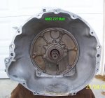
The oem stall on IH 727 converter apps is a "nominal" 1800rpm for both sii and fullsize. That can vary by 100rpm or more, this is not an "exact" science.

You can test yours simply by "power-braking" once the engine and tranny is fully warmed up, don't do that for longer than 10 seconds as the fluid temp skyrockets! And only do it once, just long enuff to freeze tha tach display in yore eyeballs.

This type stuff is engineered at the point of design/manufacture for the "optimum" overall drive ratio, figuring oem tire size, final drive ratio, tranny ratios in each gear, etc. And "optimum" includes projected vehicle gvwr/gcvwr (factoring a trailering capacity), and the engine specs/torque peak/rpm for the same vehicle.

All that hocuspocus figgrs into the various weight ratings, etc. Just as does/did, axle capacity, spring capacity, brake capacity, frame capacity, engine cooling system capacity, etc.

Of course ya can have any converter "built" to most any spec ya wanna pay for! Major deviations from all the above and including a "built" motor could certainly enhance overall vehicle/tranny performance for "some" specific applications...serious rock crawl, serious tow rig, drag race only, sand runnin' with paddle tires, etc. But then it won't be optimum for all ranges of uses/activities!

One of the largest torque converter builders in the western u.s. Is located in eugene and can do anything ya wanna pay for. Nearly all tcs sold in local/regional tranny shops come outta that facility. They are manufacturers/wholesalers only, don't sell to the walk-in trade, only commercial shops and re-distribution operations. Give 'em a spec, they'll build it (within reason of course).

There are many converters for chrysler apps available over the counter in any stall ya want. But there is a market for those. There is only one stall normally found over the counter for IH schnizz (and that's oem), since there is no market for that stuff! Simple fact of sales economics!

This topic goes round and round occasionally, just like the "motorhome" low gear set that is stuff of legend!
 
Gud tuh kno! I had my suspishuns. I wuz just curious. Lends a degree of credence to the answer I chose to provide in that bb thread.
 
Back
Top