T407/TF 727 DIY Reseal

so I don't need to make some ultra trick bearings for this thing?

Only if we gut out the entire tranny for a build-up! Based upon yore work order we ain't doin' that now.

But...if ya kin git to work on all them plastic tapered rollers and loose rollers in that 205, we'll dam shore do one!

The input system to the transfer case on this setup is very different fromma sii married mashup. That's why it's got that dam longazz "adapter" piece that just adds to the tailhousing.
 
Finally got back to t's tranny package so I can get it finished and delivered to him before xmas!

Lottsa interest lately in how to deal with fluid leaks in the area of rotating components interfacing with an oil seal...transfer case input/output shafts, axle pinion seals, transmission output shaft, etc. So let's look at a typical output shaft seal service procedure.

The system we're dealing with here is a np 205 married transfer case bolted to the azzend of the tf 727 tranny. Very similar to what ya find inna stocker Scout II witha slushbox and d20. This dodge/cummins version uses a conventional "bolt-on" output yoke for the rear driveshaft, and a bolt-on front output shaft flange which interfaces with a cv joint. These of course are not "slip" yokes and are retained to their respective shafts through a spline system with nut.

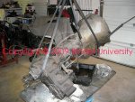
Here's a pic of the package in "before" mode for reference.
 

Attachments

  • W250 Cummins Trans 008.jpg
    W250 Cummins Trans 008.jpg
    114.6 KB · Views: 4,772
After removing both front and rear output yokes and seal/bearing retainers (those are cast aluminum in this case), the parts are cleaned and readied for inspection. We're looking for any cracks or distortion in the retainers, stripped bolt or hole threads, etc. The old retainer gaskets are also scrapped/removed from transfer case and the bearings inspected.

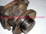
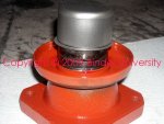
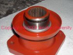
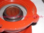
Once the front cv joint coupling was cleaned, the reason for fluid leakage from that point was real obvious! Notice the groove worn into the machined surface, that was caused by grit embedding in the seal interface and turning to lapping compound when mixed with a bit of gear lube! If ya just install a new seal here, it will quickly fail and the leak will return in short order. So we either need to replace the coupling witha new one...or fix it!

This is a budget buildup...so we're gonna fix it using a common shop technique used with engines, transmissions, etc. That have this same condition.

If you can see a discoloration of the machined surface but not feel it with your fingernail, then cleaning the surface and replacing the seal will work. If any groove or wear can be felt, then that surface must be delt with.
 

Attachments

  • NP 205 front Yoke.jpg
    NP 205 front Yoke.jpg
    101.2 KB · Views: 3,817
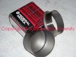
Here's the service part we use to repair damaged rotating components when possible. It's generically known as a "speedi-sleeve" from skf or a "redi-sleeve" from national/federal mogul.

skf | about us

A very thin stainless steel "bushing" with a highly refined surface finish that replicates the oem shaft/journal finish. These devices are pressed over a rotating machined surface after cleaning and prep. Full instructions are enclosed with each part, and they include a installation tool.

While not an inexpensive part, they are capable of salvaging a component which otherwise could cost hundreds of dollars to deal with in any other manner. Typical cost is $18>$40 depending upon size and location where it's to be used.

These items are designed for a range of shaft/journal dimensions, so ya gotta measure your damaged part at several points and determine if it's a candidate for repair. Then the appropriate part is selected for installation. So it's a must that you either have a micrometer or caliper for measurement, or have a pro perform the inspection/selection process for ya. In this case, the flange journal measured 1.878" nominal which is right at the top of the tolerance that this part selected can deal with.
 

Attachments

  • Redi-Sleeve 2.jpg
    Redi-Sleeve 2.jpg
    109.3 KB · Views: 2,327
The steel "cup" included with the repair sleeve is the installation tool. It's sized to push on the flange on the sleeve and then a hammer is used to force the sleeve into installed position.

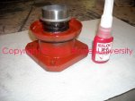
I use an anerobic locking compound ("loctite") to both lubricate the journal during installation, and to seal the inner gap between the journal and id of the sleeve. This is an interference fit, so some force is needed to seat the sleeve over the journal. The loctite prevents fluid migration through that "gap" in the long term.
 

Attachments

  • Redi-Sleeve3.jpg
    Redi-Sleeve3.jpg
    82.4 KB · Views: 2,227
Here's the sleeve with the tool engaged, and thread locker slathered on the journal. Simply whack it with a hammer until the repair sleeve is in proper position and then stop!!!
 

Attachments

  • Redi-Sleeve4.jpg
    Redi-Sleeve4.jpg
    80.8 KB · Views: 2,293
In this case, the sleeve could be whacked all the way to the end of the journal. That put the center area of the sleeve right in the sweet spot for contact with the replacement dual oil seals we're gonna install.

In some applications, that "flange" is removed from the sleeve after it's installed. That area is scored/undercut and a pair of needle-nose or dikes are used to perform surgery and snap it off and discard the waste. That's not needed in this case so the flange can be left in place.

At this point, the drive flange is now repaired and is ready for re-install. Cost for that redi-sleeve was $21...cost for a new coupling...$38>$49 depending upon source.
 

Attachments

  • Redi-Sleeve5.jpg
    Redi-Sleeve5.jpg
    77.9 KB · Views: 2,198
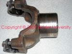
Here's a shot of the rear output yoke, this one is perfectly acceptable for re-use with a replacement seal system.
 

Attachments

  • NP 205 Rear Yoke.jpg
    NP 205 Rear Yoke.jpg
    92.7 KB · Views: 2,275
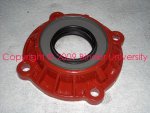
Now let's look at the seal replacement deal. First, the front output bearing/seal retainer seal "set". This is the are which was heavily leaking due to the damaged cv joint coupling that we just fixed.

The retainers/seals/output shafts, etc. On a NP205 can vary somewhat from version-to-version, same as for the type/size of coupling being used on the outputs. So this is for this particular dodge app, I'm not providing p/n for the seals, etc. Since what will vary with application! That is why ya must inspect what ya got first before obtaining the service parts! So much of what we deal with in the IH world has been juryrigged and infected with po virus, there is no telling what part you May actually need unless ya know it's original and what the transfer case came from!

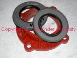
This 205 was oem with a single seal used in the front output retainer. An "upgrade" that can prevent the damage we saw in the coupling, and greatly enhance service life of that area regarding oil leakage, is to install two seals, that are thinner in case thickness. And we're gonna slam one of 'em in backwards!

Common lip seals such as those shown have a single lip that is installed with the lip pointing at the "wet" side of the application. So we are gonna knock in one of the thinner seals just like it was an oem item. The retainer has a counterbore machined in, so that first seal is gonna git knocked in all the way until it stops.
 

Attachments

  • Front Output Bearing_Seal Retainer1.jpg
    Front Output Bearing_Seal Retainer1.jpg
    99.5 KB · Views: 2,272
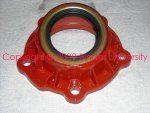
Here's the first seal installed, this is the one that will keep lube inside (hopefully!) the case.

The duplicate seal will then be installed upside down and knocked in until there is a slight space between the seal cases, do not knock it in until it won't move any more!!!!! We want some space between the seals in case we need to "adjust" it later.

The idea here is to use the second seal as a "dust excluder" (a misnomer since what we're hoping to exclude is mud, rustbugs, water,sand, gravel, chupacabras, guapo, etc.).

If ya can source a double lip seal which is designed in the same manner, then it could certainly be used also! Since t's business is bearings, seals, and all the related guapo what goes with that, he's the repository of all the knowledge base for shit like this so I bet he can find us an even better system for this application. But...what we got here will last his lifetime (but maybe not jen's!).

And to make this all relevant to a Scout II transfer case setup, this is exactly the same type seal system that is used in the output shaft/transfer case adapter behind those "special" output shaft bearings that terry manufacturers exclusively for ihon!
 

Attachments

  • Front Output Bearing_Seal Retainer2.jpg
    Front Output Bearing_Seal Retainer2.jpg
    96.8 KB · Views: 2,300
Here's the completed second seal installation, this seal is knocked in until the edge of the case is just flush with the outer edge of it's counterbore.
 

Attachments

  • Front Output Bearing_Seal Retainer3.jpg
    Front Output Bearing_Seal Retainer3.jpg
    98 KB · Views: 2,299
Now, I've stuck the repaired coupling into the seal interface and pushed into approximate position of where the coupling will be located within the seal system. Ya can see the end of the repair sleeve protruding from the seal lip and shows we got plenty of engagement of the seal lip and sleeve...just right!

So there is no need to "adjust" the position of the two seals, now this retainer is ready for re-installation. Lucked out here, this has nothing to do with skill! Skill means ya always source multiples of any part like these seals so that when ya fuck up the first set, ya gotta another set to use after yore learning experience. Or in my case, I set 'em down somewhere and kain't find 'em until next month and they show up like majik in the refrigerator or beer cooler.
 

Attachments

  • Front coupling position.jpg
    Front coupling position.jpg
    88.4 KB · Views: 2,168
Now let's do the rear output retainer seal install.

In this case, the replacement seal is a kinda "double lip" version that has an hd lip for keeping lube in, and a hd lip for keeping mung out. So no need to do the double-up deal here! And...the front output and rear output seals are different in size, they don't interchange on this particular 205 case, but on some versions they May.

So this is a straightahead, knock in the seal until it bottoms in it's counterbore kinda deal.
 

Attachments

  • Rear Output Bearing_Seal Retainer.jpg
    Rear Output Bearing_Seal Retainer.jpg
    102.4 KB · Views: 2,270
Next up ya simply re-install the two seal/bearing retainers to the clean case mating surfaces! No pics of that, if ya can't figgr it out, ya shoulda had a pro do this job!

Use a new gasket (front and rear gaskets are completely different!) with no sealant needed. Above all...do not ever use rtv on those flanges, no matter what ya do it will extrude and contaminate the bearing(s) and block the lube return port in the casting. The gasket also serves as a distance piece for the bearing being retained against it's peripheral snap ring, it serves as a "shim" and must be used. That bearing "floats" in it's bore and is not a press fit in the case.

Also I always use loctite on the bolt threads, prevents backing out and seals the threads against lube migration past the threads and bolt head when tightened.
 
One final area to address...the np 205 uses rubber seal "washers" that are slipped over the spline after the coupling or yoke is installed. And again, the sizes of each are different.

These seals prevent lube migration down the splines of the interface and past the retaining nut. A small detail often overlooked.

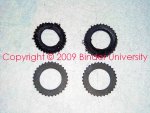
This shot shows the old seals that are badly damaged/distorted, along with a new pair of replacements. These are not simply some kinda hose washer, they are engineered with internal and external spline segments designed to fit this application!
 

Attachments

  • NP 205 Output Spline Seal.jpg
    NP 205 Output Spline Seal.jpg
    102.2 KB · Views: 2,273
nice! Wasn't expecting a tc overhaul too!:thumbsup:

Leaks is leaks dude! Ya said seal tha bitch...so ya gitta bitch back that's sealed!

We don't work like a reglar "for pay" shop around here, we fix shit right and also fix shit before it's broke if we can 'member what is gonna break! But I do take lotssa naps in between fixxin' broke shit!
 
We're gittin' close to tha end now, two more leaks to address.

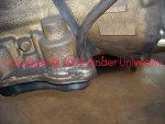
The dip stick tube is a major leaker on these trannys if not fixed as soon as a leak starts. The seal for the tube is a simple "o" ring placed into a neckdown portion of the tube, then the tube is stuck into a hole that has a heavy chamfer on top to guide the "o" ring in. The tube is retained in place by a stay welded to it, that is retained by one of the bell housing-to-block bolts.

This one shows a heavy accumulation of grunge...that needs to be cleaned away before removing the tube so shit don't fall inside the pan.
 

Attachments

  • Dip Stick Tube Leakpoint.jpg
    Dip Stick Tube Leakpoint.jpg
    125 KB · Views: 2,298
Just pull up hard on the tube and it will pull out of the hole. If tranny fluid is still in the pan, it will pour out! So it's best to re-seal the dip stick tube while the pan is down for service.

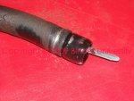
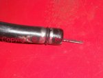
Here's the old tube seal, the "o" ring has turned square and hardened from heat and age.
 

Attachments

  • Damaged Dip Stick Tube O Ring.jpg
    Damaged Dip Stick Tube O Ring.jpg
    83.5 KB · Views: 2,382
Remove the damaged "o" ring and discard. Then clean the tube very well, inside and out, along with the dip stick itself.

Many times you will find all kinds of "sealers" slathered around that area, especially fuckin' rtv. All that shit must be completely removed and the metal nice and bright!

Clean really well around the tranny hole also, and remove any sealer residue. The hole must be clean in order for the new "o" ring to seal.

Then simply slide a replacement "o" ring over the tube and seat it in it's groove.
 

Attachments

  • Replacement Dip Stick Tube O Ring.jpg
    Replacement Dip Stick Tube O Ring.jpg
    71.6 KB · Views: 2,345
Common practice when doing an r&r on any tf 727, is to remove the dipstick before dropping the tranny out. That way the dip stick won't hang up on anything and get damaged.

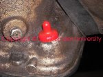
Since this powertrain is going into a total custom install inna sii, I've put a temp plug in the tube hole to keep the mice out. Once t gits the package installed for the final time, he can install the tube in position...in fact, he May end up having to relocate the tube or even eliminate it if it poses an interference issue with the body. That temp plug will not serve as a permanent plug, it will blow right out once the tranny is placed in operation.

When re-installing the dipstick tube, don't evewr use rtv! It will get inside the trans!

I use either permatex #97 or hylomar on the "o" ring in this location, that "lubricates it when moving into position, and then forms a resilient bond between the "o" ring, the tube, and the hole.
 

Attachments

  • Dip Stick Tube Hole Sealed.jpg
    Dip Stick Tube Hole Sealed.jpg
    113.2 KB · Views: 2,256
Last edited:
Now...our last leak point...and also the most common. It's often mistaken for a rear crankshaft seal leak.

This is referred to as the "front pump seal" most commonly, some call it a "torque converter seal", or an input shaft seal. It actually seals the snout of the torque converter when it rotates in the front pump and takes a tremendous amount of abuse! And of course sees a significant pressure behind it.

The primary reason the seal eventually fails (other than po virus fuckin' it up when a tranny is r&r'd), is because the bushing in the pump that supports the converter hub wears out. So when the seal is replaced, the bushing is commonly replaced also. That can be done from the outside, no need to remove the pump to do that.

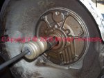
Easiest way to remove that seal is with the seal puller attachment that is normally part of a small slide hammer set. The "hook" tool.

Carefully insert the hook tool between the shaft and the seal lip, twist to engage the metal case and lip of the seal, and pop it out, a very ez job and no surprises will jump out at ya!
 

Attachments

  • Front Seal Remove.jpg
    Front Seal Remove.jpg
    131.1 KB · Views: 2,465
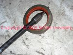
Here's a better shot of the seal hook, slide hammer, and failed seal. That seal is a silicone rubber item, and can tolerate extreme heat conditions. Sometimes the replacements are green in color, sometimes they have a small flange to prevent driving in to deeply, there is no preference for which seal is used, I use any seal I can get from the supplier at the time. And for the 727, that seal has not changed since 1965 or so!
 

Attachments

  • Front Seal Removed.jpg
    Front Seal Removed.jpg
    140.1 KB · Views: 2,282
Back
Top