Rebuilding an NP202

attachment.php

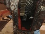
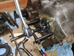
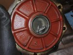
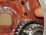
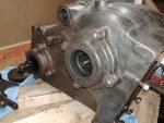
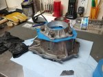
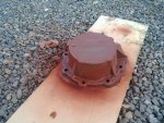
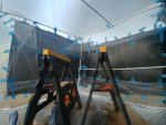
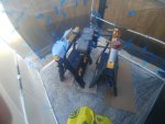
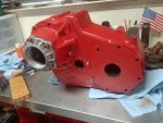
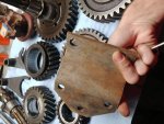
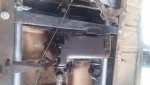
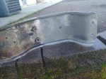
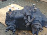
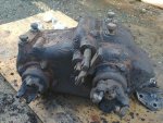
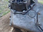
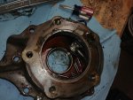
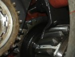
I will be doing a full rebuild on this unit, its already removed, and is factory original to the truck it was pulled from(1965 1100). Leaks like a civil servant, and possibly has bearing noise(its either the drivelines or these bearings). The first step is to ensure there actually is a transfer case somewhere encased in this glob of road grime:
attachment.php

attachment.php

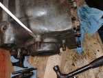
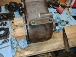
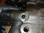
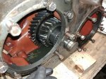
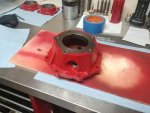
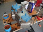
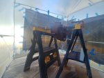
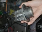
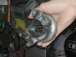
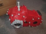
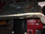
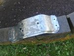
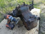
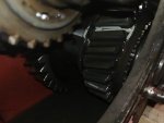
The gunk is strong in this one... Here it is after some screwdriver scrubbing:
attachment.php

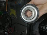
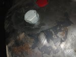
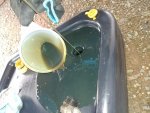
Here is the oil that came out of it, not the greatest ever, but couldve been nothing in there so I'll take it:
attachment.php

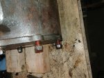
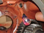
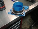
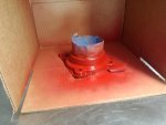
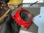
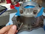
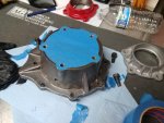
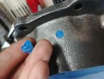
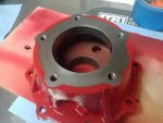
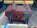
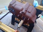
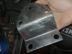
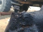
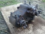
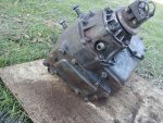
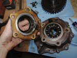
I've found evidence of both red and black paint under the grime, with some careful scratching I could tell the red was underneath the black and looks to be in a similar condition to the paint on this trucks 304 engine, so that will be the color of the new paint:
attachment.php

On that note, I'm a knownothing in regards to under body painting, nor do I have a spray gun, anybody out there who knows a good/cheapish DIY method feel free to educate me :D 
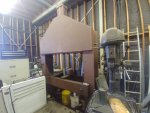
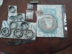
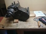
cheapish said, I want to do it right; I dont want to skimp anything and it needs to be durable. I have a kit on the way with seals, bearings, and small parts, I will be fabricating a couple gaskets not included in the kit and will likely need to fabricate the bearing retainer gaskets in their correct thicknesses as well. Right now I'm just waiting on a muscle bound minion to help me pick this dadgum heavy thing up and get it on a bench, and the rebuild kit itself.
Edit: just for the record, the history I've been told on this truck is that it was owned by a telephone company for line maintenance, and heavy use of a pto winch. So consequently its high hours, but relatively low miles at around 45k
 

Attachments

  • 20181126_143552.jpg
    20181126_143552.jpg
    73 KB · Views: 4,222
  • 20181201_131221.jpg
    20181201_131221.jpg
    102.3 KB · Views: 5,539
  • 20181201_131229_HDR.jpg
    20181201_131229_HDR.jpg
    87 KB · Views: 4,299
  • 20181201_134051.jpg
    20181201_134051.jpg
    105.4 KB · Views: 4,853
Last edited:
Lol just noticed most of the above pics are broken. *FIXED
Back from the holidays, with an update on this project. My removal method was sketchy at best, and haphazardous at worst so I will let you assume the much improved reverse of install is a good way to remove it. Where I'm currently at isnt too much better than where I left off, I'm trying to find a 1 5/16" socket that will fit inside the drive yokes. Here it is 90% clean atleast:
attachment.php

Gunk removal consisted of a worn out wire wheel, cordless drill and a butt ton of drill batteries. Works exceedingly well. Note the brownish powder eveywhere:
attachment.php

attachment.php

attachment.php

attachment.php

One note on this method, avoid the alluminum flange on the output shaft, the wire erodes it very easily. With a little research here and on Binder Planet I found out that these units left the NP factory with a red oxide primer/rust prevention type paint, and were sprayed black as a sub assembly at the IH factory. I will be using red oxide enamel based paint as the under coat of all the cast parts, then painting it IH red. I'm going with the red because its much easier to spot leaks, and it will look nicer when its clean.(AND IT MATCHES THE ENGINE/TRANS BECAUSE OCD) I may use a bit of black paint here and there, but probably only for limited aplications where leaks cant start. Luckily for me and my imaginary/non existent spray gun, both the red oxide and IH red enamel were available in rattle cans from my local Tractor Supply Co, a format I'm extremely experienced with. I can personally attest to the fact that you can indeed get uber high quality mirror like finish with the right technique using rattle cans, not that it matters too much on this type of part. I've heard people say otherwise, but its a myth because I've done it before.
*also, mods feel free to insert a shameless IHPA add here if you stock these paints as well, I just havent had time to make it back up to Grass Valley yet.
This truck is (the story goes) low milage, high hours, and though it probably doesnt need bearings, due to the wear in the drive shafts, I'm replacing them anyways. The kit is from Torque King 4x4, and includes the pto gasket even though it says that it does not on their website. I can't remember wich one it was, but I did inquire about the manufacturer of the bearings, and they are one of the higher end Japanese makes. In my case the low gear rollers are refurbished NOS due to the current availability.
Here is the kit:
attachment.php

The shaft seals are good quality, however they are not the original type. The original seals are 0.5 thick and have rubber on the inside to keep oil in and felt on the outside to keep dirt out. I'm in contact with a member of Binder Planet who came up with a way to replicate this, and will post up a link/more about it later on with his permission(his idea not mine, if he does a write up I will post a link to it here once my new seals come into play). More to come soon on this one, I just need to find the right socket.
 

Attachments

  • 20181211_121404.jpg
    20181211_121404.jpg
    130 KB · Views: 4,620
  • 20181211_145331.jpg
    20181211_145331.jpg
    115.4 KB · Views: 4,058
  • 20181211_145325.jpg
    20181211_145325.jpg
    124 KB · Views: 4,070
  • 20181211_145341.jpg
    20181211_145341.jpg
    77.6 KB · Views: 3,928
  • 20181211_145350.jpg
    20181211_145350.jpg
    126.7 KB · Views: 4,186
  • 20181223_152058.jpg
    20181223_152058.jpg
    65.1 KB · Views: 3,798
Just find a socket you don't care much about and grind/sand/turn it down to where it fits. If you don't have a lathe, grinding it on a bench grinder or belt sander while you turn the socket until you get it to where it will fit the yoke.
 
THE HAAAUUULKKK
RRRRRAAAAAAAAWWWWWWWRRRR
FINALLY the dive yoke nuts just came off and I can start on the fun part of this project. Giant impact driver for the win!
*Note to Jeff's coment: that was one of my ideas but a socket from napa ended up fitting perfectly.

Awlrighty, step one as you could probably figure out, remove the cotter pins/castle nuts from the yokes. Once their off, the yokes slide right off the shafts. This produces a weird smell that I can only describe as somewhere between camp fire and bad bacon. I didn't have my instructions for disassembly with me today so I only went as far as I could remember. With the three yokes removed, I took a minute to remove some other unnecessary external parts, such as the remaining parts of the linkage and the mounting bolts I put back in to keep dirt and water out. The first big step is to remove the 8 bolts (two are nuts on studs) and pull the rear output shaft assembly. E.G. the big hunk on the left:
attachment.php

*Important note: I DID THIS WRONG! Before removal, install the yoke and screw on the castle nut. I poped the housing loose by tapping on a lip that overhung the edge of the case, however because I already removed the nut/yoke, the shaft stayed in the case and needle bearings went everywhere inside the assembly. Not a huge deal, the parts inside misaligned so I didnt see the order they were in, but I was able to figure it out. Here you can see the rear shaft and assembly, note the small pile of rollers came from the back side of the big drive gear, integral to the shaft:
attachment.php

attachment.php

attachment.php

These thinner rollers were the ones that fell out, I found them as I disassembled the housing:
attachment.php

The alluminum flange with the seal comes off first, I'm not confident this had the original seal, the road grime wasnt as strongly stuck here as elsewhere, nor was it the proper thickness to be fully seated in the alluminum flange:
attachment.php

Next up, a small ring is removed and the main bearing is pulled:
attachment.php

attachment.php

Once this bearing is removed, the spacer and worm gear for the speedo drive can be lifted out, and here I found the rest of the needle bearings:
attachment.php

attachment.php

I removed the breather vent, 7/16 size, mine will need to be taken apart and cleaned or replaced:
attachment.php

The last thing to remove with acception of the speedo drive(didnt have the right socket with me) is the roller bearing cup where all the loose rollers originated from. Worth noting, this was significantly more difficult to remove than the main bearing:
attachment.php

Last thing I did today was remove the pto cover for some pictures:
attachment.php

attachment.php

attachment.php

On the inside of the housing the finish is very nice, all I'm going to do with the case itself is degrease once its bear, tape up all seal/mounting surfaces and paint the outside. Final note, my rear yoke is broken, so I will be sourcing a new one, more to come on that. Also sorry the pics are dark, I'm working in the barn for this and forgot to turn on the flash for some of em.
 

Attachments

  • 20190102_143948.jpg
    20190102_143948.jpg
    53.2 KB · Views: 3,717
  • 20190108_142753_HDR.jpg
    20190108_142753_HDR.jpg
    80.1 KB · Views: 3,594
  • 20190108_142838.jpg
    20190108_142838.jpg
    71.7 KB · Views: 3,585
  • 20190108_142845.jpg
    20190108_142845.jpg
    59.3 KB · Views: 3,592
  • 20190108_142952.jpg
    20190108_142952.jpg
    43.7 KB · Views: 3,565
  • 20190108_143818.jpg
    20190108_143818.jpg
    76.3 KB · Views: 3,520
  • 20190108_143808.jpg
    20190108_143808.jpg
    61.1 KB · Views: 3,543
  • 20190108_143651.jpg
    20190108_143651.jpg
    70 KB · Views: 3,533
  • 20190108_143140.jpg
    20190108_143140.jpg
    62.1 KB · Views: 3,531
  • 20190108_143018.jpg
    20190108_143018.jpg
    82.2 KB · Views: 3,543
  • 20190108_144137.jpg
    20190108_144137.jpg
    69.4 KB · Views: 3,455
  • 20190108_144808.jpg
    20190108_144808.jpg
    78.9 KB · Views: 3,401
  • 20190108_150615.jpg
    20190108_150615.jpg
    62.1 KB · Views: 3,491
  • 20190108_150628.jpg
    20190108_150628.jpg
    54.7 KB · Views: 3,429
  • 20190108_145608.jpg
    20190108_145608.jpg
    46.7 KB · Views: 3,424
  • 20190108_145555.jpg
    20190108_145555.jpg
    32.8 KB · Views: 546
  • 20190108_150706.jpg
    20190108_150706.jpg
    64.7 KB · Views: 571
Nice write up and puller set! Good to know on the Napa socket.

The reason the smaller needle bearings fell out was due to that bearing being worn out.

Now back to your rebuild.
 
Jeff, remind me later if I forget, I'll post up info on the tools I used. Believe it or not that puller is Harbor Freight, nicest thing I've ever got from them by far. I was wondering about that bearing since its one piece in my kit.
 
Update for the last bit of tech, this is usually done along with the above before moving on but I didnt have the tool with me.

Removed the speedometer drive from the housing(15/16) it poped loose with a breaker bar and a size 13 boot standing on it.
attachment.php

To remove the input shaft assembly, the first step is to remove the detint assembly for the shifter bar. This broke loose easily and revealed the spring and ball. These will be replaced, the springs are known to break, and the balls obviously wear, neither one look bad but best to use new components anyways:
attachment.php

The next step is to remove the roll pin that secures the shift fork to the shift bar, the instructions say to work through the hole where the rear output assembly was. This is physically impossible because of the extream angle of the punch or 5/16 bar relative to the hole. With the shift bar fully foreward I used a roll punch and a rachet extension to drive out the pin straight through via pto port:
attachment.php

Unfortunately I didn't figure this out initially and spent about 2 agrivating hours smashing my fingers every other attempt or so and with various roll pin punches being trolled by a roll pin (troll pin?) that apeared cemented in place with no good way to drive/drill it out. Uppon first aplication of my extended punch meathod the pin drove straight through, all the way, with one firm swing like it had just been freshly installed. Once the troll pin was out(doesnt come fully out, stops against the case) the bar can be pulled out the front and the input shaft can be slid rearward through the gears out of the main bearing and the cluster dropped into the case for the fork to be lifted up and out. Once again, this can be done(maybe) without rollers going everywhere.... Good for you if you manage it :lol: 
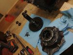
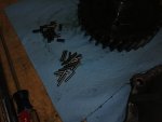
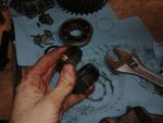
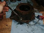
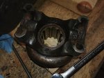
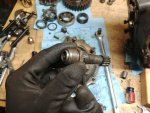
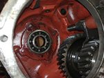
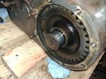
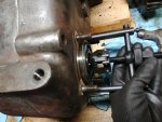
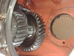
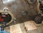
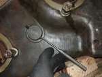
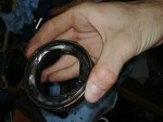
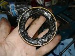
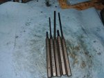
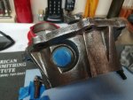
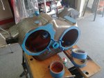
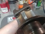
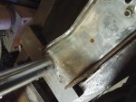
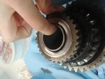
mine didnt come out in one piece. Theres currently around 10-20 rollers submerged in the excess oil at the bottom of the case. Also my phone died while I was removing the troll pin so I will have to grab more pics for an update on these steps. :mad2: 
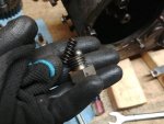
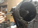
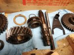
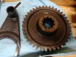
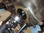
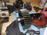
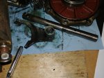
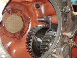
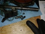
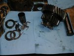
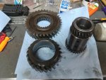
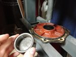
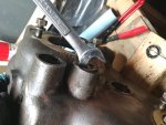
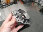
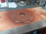
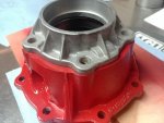
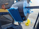
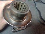
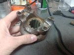
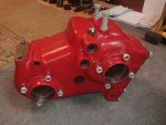
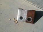
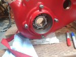
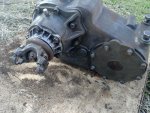
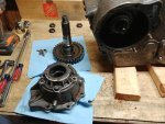
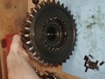
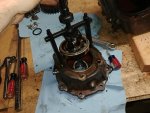
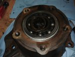
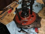
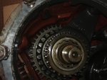
The shaft assembly comes out through the rear output hole, and leaves the pto drive gear behind to come out through the pto port. All the remaining components simply slide off the shaft. At this point I would be removing the input bearing retainer, followed by pulling/inspecting the main bearing and seal, but I havent done that yet because I ran out of time
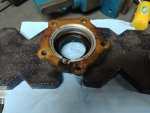
 :mad2: I'm going to enjoy hammering that roll pin flat later. . . .
 

Attachments

  • 20190109_163742.jpg
    20190109_163742.jpg
    74.7 KB · Views: 3,286
  • 20190109_163757.jpg
    20190109_163757.jpg
    57.2 KB · Views: 3,366
  • 20190111_162951.jpg
    20190111_162951.jpg
    44.2 KB · Views: 3,326
Pics of the input components, here is the shaft, drive gear, shift fork, shift bar, and a couple things I forgot the names of :icon_xp:
attachment.php

Here we see the PTO drive gear, it lives all the way foreward on the shaft as seen in the second pic through the pto port:
attachment.php

attachment.php

And here the void in the case behind the input main bearing:
attachment.php

Refer to reassembly for the complete input cluster assembly(sorry, phone died before I could get more pics)
Next up, off with the bearing retainer, four simple nuts and a light tap on the edge with a screw driver to pop it off:
attachment.php

Then the bearing is pulled and inspected. Worth noting, this one had the least feelable play in it, it was still quite tight. Also, this one did not want to come easy, and made an audible snap as it broke loose:
attachment.php

attachment.php

This completes the input shaft assembly removal. Stand by for foreward output disassembly...
 

Attachments

  • 20190114_131805.jpg
    20190114_131805.jpg
    84.9 KB · Views: 3,204
  • 20190114_131810.jpg
    20190114_131810.jpg
    74.4 KB · Views: 3,191
  • 20190114_131818.jpg
    20190114_131818.jpg
    77.5 KB · Views: 3,258
  • 20190108_150615.jpg
    20190108_150615.jpg
    62.1 KB · Views: 3,172
  • 20190114_133017.jpg
    20190114_133017.jpg
    83.2 KB · Views: 3,217
  • 20190114_132915.jpg
    20190114_132915.jpg
    102 KB · Views: 3,256
  • 20190114_132632.jpg
    20190114_132632.jpg
    90.6 KB · Views: 3,188
Forward output shaft disassembly, easier than you think!
Start by unbolting the rear bearing retainer (tech note/ this was the first evedence I noticed of thread sealant of any kind) and taping lightly on the front of the shaft untill the bearing retainer's shoulder comes out:
attachment.php

attachment.php

The rear bearing retainer is then simply pulled off the shaft, once again, the captured roller bearing immediately fell apart:
attachment.php

Then the gear/shaft comes out in one pice (carefull, its about 40% of the entire weight of the whole t-case):
attachment.php

attachment.php

Next up, same bearing retainer business as the input shaft, this bearing was tight, not as much as the input. It came out little resistance, I put the puller on and tightened the collar by hand to seat it when I noticed it was just sliding right out:
attachment.php

This was by far the easiest part of this whole process. Stand by formore...
 

Attachments

  • 20190114_133813.jpg
    20190114_133813.jpg
    73.8 KB · Views: 3,107
  • 20190114_134022.jpg
    20190114_134022.jpg
    91.1 KB · Views: 3,207
  • 20190114_134051.jpg
    20190114_134051.jpg
    95 KB · Views: 3,216
  • 20190114_134055.jpg
    20190114_134055.jpg
    80.6 KB · Views: 3,183
  • 20190114_134252.jpg
    20190114_134252.jpg
    91.2 KB · Views: 3,184
  • 20190114_135807.jpg
    20190114_135807.jpg
    69.1 KB · Views: 3,218
Idler shaft/gear/shifty thingy:
Roll pin number two comes next, I pushed the shifter bar all the way forward and drove it out through the pto port, the shift bar can then be pulled straight out and the fork rotated and removed:
attachment.php

attachment.php

attachment.php

The poppet ball will be loose in the bore once the bar is pulled, I simply rolled it out into my waiting hand by tipping the case, the spring and shift bar interlock pin are not so eailly removed:
attachment.php

The interlock pin stays put due to residual goop, I lifted the spring upward with a standard driver and used it to push the pin upward and held it there with a stubby driver. This allowed the end of the pin to protrude upward into the upper shift bar bore, where I lifted it out with a finger and reeeeeaally long thin driver from the other side. I just scooted it up till it misaligned and picked it out through the cap screw hole with a magnet. The spring simply came out of the bore when I removed the stubby driver:
attachment.php

attachment.php

attachment.php

From here we remove roll pin #3 from the idler shaft, I chose to go at it from a weird angle just because the end was inside the hole and there was no chance of mushrooming it:
attachment.php

Once the pin is out, the shaft is simply pushed through the case with light tapping, and pulled out. The gear assembly is then lifted out through the rear output opening:
attachment.php

attachment.php

The assembly can be removed in one piece. . . again. . . good luck with that. Mine came out as you see here:
attachment.php

The sliding gear assembly is seperated by first removing the snap ring and application of a couple wood blocks and a rubber mallet. Note no rollers inside, I thought there were, in that regard it may not be worth the effort to take this apart:
attachment.php

that is the final step for disassembly. The stripped case weighs by my guess roughly 35-45 lbs so its much easier to manipulate for draining the remaining oil/roller bearings/dirt as well as for paint and prep.
 

Attachments

  • 20190114_141456.jpg
    20190114_141456.jpg
    79.4 KB · Views: 3,077
  • 20190114_141445.jpg
    20190114_141445.jpg
    78 KB · Views: 3,060
  • 20190114_140137.jpg
    20190114_140137.jpg
    61.2 KB · Views: 3,099
  • 20190114_140128.jpg
    20190114_140128.jpg
    83 KB · Views: 3,096
  • 20190114_141634.jpg
    20190114_141634.jpg
    74.2 KB · Views: 3,081
  • 20190114_141641.jpg
    20190114_141641.jpg
    82.3 KB · Views: 3,058
  • 20190114_141823.jpg
    20190114_141823.jpg
    69.5 KB · Views: 2,947
  • 20190114_143057.jpg
    20190114_143057.jpg
    62.2 KB · Views: 3,029
  • 20190114_142611.jpg
    20190114_142611.jpg
    85.7 KB · Views: 3,271
  • 20190114_142346.jpg
    20190114_142346.jpg
    82.1 KB · Views: 3,021
  • 20190114_142102.jpg
    20190114_142102.jpg
    89.4 KB · Views: 3,020
  • 20190126_140041.jpg
    20190126_140041.jpg
    77.5 KB · Views: 2,850
Last edited:
And I was wrong. . . about the last step thing, the seals still need to be removed, along with the body of the bearing assembly from the forward output shaft rear bearing retainer. . . woohoo thats a mouthfull, reminds me of my days at North Mid Valley South Middle School :crazy:
Anyways, the bearing assembly body is straight forward enough, presses right out:
attachment.php

The two forward main seals are removed by applying pressure via press to the inside face on one side untill it begins to deform, then relase and rotate slightly, repeating untill it starts to press out. The seal looks like this when it works:
attachment.php

When the face deforms without breaking loose, the press arbor slips off. When this happed on the second seal, I resorted to a brass punch and 10oz ballpein. Then the end of my punch deformed so I switched to a hardedned steel punch. Then I steped up the hammer size to a 18oz crosspein. Then I got angry and the punch punched a hole or three but it finally came out :icon_xd: here is what the seal looks like when you didn't remove it properly:
attachment.php

The rear output seal has been replaced with a modern type seal that lacks the felt and 0.5" thickness of the original two. I already figured it was a modern replacement without even looking at it. The rear yoke with its evedence of having blown off a u-joint at some point:
attachment.php

and the fact that the nut was 5x tighter than the others were evedence enough of yet another round of PO's botched and utterly #@×%ed up tinkering. That seal simply pressed out with a brass punch:
attachment.php
 

Attachments

  • 20190114_153106.jpg
    20190114_153106.jpg
    50.5 KB · Views: 2,865
  • 20190114_162802.jpg
    20190114_162802.jpg
    47.6 KB · Views: 2,914
  • 20190114_164135.jpg
    20190114_164135.jpg
    75.1 KB · Views: 2,902
  • 20190114_153211.jpg
    20190114_153211.jpg
    70.4 KB · Views: 2,908
  • 20190108_150706.jpg
    20190108_150706.jpg
    64.7 KB · Views: 2,928
Last bit here before paint prep starts(will update the post above with the sliding gear assy when I press it apart tomorow). The unit is now fully disassembled, the last bit went as follows:
Shift bar seals come out easy with a box end wrench(IF you dont plan on reusing them):
attachment.php

The bearing puller I used:
attachment.php

attachment.php

I forgot to get a pic of the socket I used on the drive yoke nuts, the brand is Carlile I think, 1 5/16, got it off the wall at napa.
*Carlyle SD12042 1/2" drive 6 point*
Note to the "average dude" looking to do this. Do it at your own risk, I'm not a pro by any standard. Know your limitations, but dont be afraid to try. I personally have a knack for making piles of parts out of mechanisms and putting them back with no instructions. Basically, I can figure the order and proper placement of parts just out of practice and simple observance. If you can do that great, if not, have a friend take pictures of the parts as they come out for assembly purposes. Pics are your best friend here, even in addition to the service manual. Short of a buddy to help me remove this from the vehicle, and pick it up onto the bench, I've done ALL of this BY MYSELF and with my own two hands; no camera man (my cell phone got verry oilly in the process). Outside of what I consider to be the "average guy's" toolbox and apart from the shop press, I have the afore mentioned socket, a few roll pin punches(pictured below, I've had a set of these for gunsmithing although I've never used these big ones before) the bearing puller, snap ring pliers, and the impact driver I used. I did all of this, in this space(apart from paint of course) note the two size 13s on the floor, theres room enough for maybe two people infront of this bench, and its also storing an ancient computer on the end. Hows that for cramped?:
attachment.php

Sorry but you'll have to turn your head a bit lol.
There is not alot of space required to do this, and dont be intimidated by all the gears, in reality the device is quite simple. Many of these parts can only go back in one way, and carefully tackling a job like this will greatly increase your understanding of how it works. Just for the record, I've never been inside a gear box of any kind before this.
The impact driver I used was a Rigid brand 18volt. Here are what I considder the odd(er) tools:
attachment.php

attachment.php

attachment.php
 

Attachments

  • 20190125_172631.jpg
    20190125_172631.jpg
    74.1 KB · Views: 2,816
  • 20190125_172606.jpg
    20190125_172606.jpg
    69.9 KB · Views: 2,791
  • 20190125_172211.jpg
    20190125_172211.jpg
    84.9 KB · Views: 2,846
  • 20190125_172242.jpg
    20190125_172242.jpg
    74.2 KB · Views: 2,781
  • 20190125_172552.jpg
    20190125_172552.jpg
    87.2 KB · Views: 2,841
  • 20190125_172647.jpg
    20190125_172647.jpg
    56.9 KB · Views: 2,772
Last edited:
One eternity later. . .
Back to work on this grease blob I go, Ive been super busy the last couple months and this project hasnt progressed far. Currently there is a five gallon bucket of deisel and the smaller castings soaking in storage, today is the day I first attempt paint prep. More to come here very soon, stay tuned for the final epic battle against ancient road grime thats so bad, it might actually be alive. . . for now.
 
So foiled plans, and a week of pond maintenance/sunburn later I actually started paint prep. The final method was lots of wire wheel, lots of wire hand brushes, acetone wipe down till clear, tape, then FINALLY the first coat of red oxide primer. I began with the small bearing cap to start easy, and made up a mini paint booth. Heres the progression from pre removal, to relatively clean, to super clean, to primer:
attachment.php

attachment.php

attachment.php

attachment.php
 

Attachments

  • 20190623_181721(1).jpg
    20190623_181721(1).jpg
    57.6 KB · Views: 2,556
  • 20190623_183555.jpg
    20190623_183555.jpg
    33.7 KB · Views: 2,515
  • 20181201_131221.jpg
    20181201_131221.jpg
    102.3 KB · Views: 2,580
  • 20190114_131939.jpg
    20190114_131939.jpg
    80.4 KB · Views: 2,558
First coats of paint here:
attachment.php

For reference I did two coats primer and plan for three coats of paint. Slow going with paint right now, figures the one time I have a shortage of cardboard I have multiple parts to paint. Progress from here will be the other retainer, the cover behind the front output cluster, the rear output cluster housing and then the main case wich will be done "very carefully" :icon_eh2: the rear retainer I'm going to leave bare alluminum, perhaps with a rough pollish just so it looks a little cleaner:
attachment.php

Also currently in the works is de-rusting/ painting the pto port cover.
 

Attachments

  • 20190630_134202.jpg
    20190630_134202.jpg
    40.8 KB · Views: 2,424
  • 15619282276855009547009203642952.jpg
    15619282276855009547009203642952.jpg
    56.8 KB · Views: 2,398
The two front bearing retainers complete:
attachment.php

I've begun the process on the rear output housing, as well as the front ouput's rear retainer. Tapping off the housing was a little more complex this go round:
attachment.php

attachment.php

attachment.php

attachment.php

attachment.php

Painting has gone smoothly, although for lack of a big enough box I've resorted to running it outside, quickly spraying then running it back inside and setting the only box I have over it to keep dust off:
attachment.php

attachment.php

I'm planning on primering the yolks and painting them black to match my drivelines, but asside from that, the bolts and the main case are all thats left to deal with in regards to major cleaning. Today I realized I had no clue on how to effectively plaint my main case outside of my garage. Then a pile of scrap pvc fell on my head in the barn, and this monstrosity was born:
attachment.php

Hopefully it will prove a good makeshift paint booth, I plan on covering it all the way around with painters plastic and duct tape, and then anchoring it with tent stakes and rope. This is the only part I dont want to try and move in and out of my garage between coats of paint, so the plan is that this booth will hold up for atleast five days for five coats.
I'm not going to lie I'm nervous about how this rebuild will turn out but I just keep telling myself "amateurs built the ark, profesionals built the Titanic."
 

Attachments

  • 20190705_181225.jpg
    20190705_181225.jpg
    65.2 KB · Views: 2,421
  • 20190705_184604.jpg
    20190705_184604.jpg
    74.9 KB · Views: 2,410
  • 20190705_184652.jpg
    20190705_184652.jpg
    73.3 KB · Views: 2,391
  • 20190705_185237.jpg
    20190705_185237.jpg
    73.6 KB · Views: 2,352
  • 20190705_190026.jpg
    20190705_190026.jpg
    68.5 KB · Views: 2,361
  • 20190705_190356.jpg
    20190705_190356.jpg
    82.2 KB · Views: 2,395
  • 20190705_191732.jpg
    20190705_191732.jpg
    107 KB · Views: 2,372
  • 20190707_124453.jpg
    20190707_124453.jpg
    52.4 KB · Views: 2,372
  • 20190707_124005.jpg
    20190707_124005.jpg
    63.6 KB · Views: 2,368
Rear output complete:
attachment.php

attachment.php

attachment.php
 

Attachments

  • 20190710_100625.jpg
    20190710_100625.jpg
    62.8 KB · Views: 2,313
  • 20190710_100641.jpg
    20190710_100641.jpg
    52.5 KB · Views: 2,326
  • 20190710_100711.jpg
    20190710_100711.jpg
    56.4 KB · Views: 2,378
Oof. Feels like I've been on an epic journey with this thing... On to the main case! The first step was to make a safe covered area outside my garage to paint in, as this hunk is a might too heavy to be moving around with wet paint. And thus this wad of painters tape, plastic sheeting, pvc pipe and survey string was born; I call it the poor man's paint booth:
attachment.php

attachment.php

Next up for the housing was a very teadious degrease process that involved alot of steel brushes, and wire wheeling, followed by some brake cleaner, and a wipe down with acetone. Then I taped up the majority of the openings:
attachment.php

attachment.php

And moved it into position on the saw horses, supporting it with some long wood clamps I didnt care too much about(they needed wire wheeling anyways so paint didnt bother me) along with a wood block in each of the larger openings to level the case and one other block and clamp to help support the first two clamps. Once it was supported I completed tapeing around the supports:
attachment.php

attachment.php

At this point I did one more acetone wipedown, wich was mostly clean, the only grease I got was where I had been handling it between garage and booth, it all wiped clean. Last step, paint. A good respirator was used, and it stops the paint itself but not the fumes, so I limited my time in there to a couple minutes at most and not alot of breathing lol it was foggy in there by the time I was done:
attachment.php

attachment.php

attachment.php

Tons more to come on this, first coat of IH red is drying as I type, and the hard part is almost done. Once everything is painted it will start going back together!
 

Attachments

  • 20190920_184719.jpg
    20190920_184719.jpg
    108.2 KB · Views: 2,281
  • 20190920_184647_HDR.jpg
    20190920_184647_HDR.jpg
    64.5 KB · Views: 2,275
  • 20190921_105738.jpg
    20190921_105738.jpg
    89.2 KB · Views: 2,287
  • 20190921_123359.jpg
    20190921_123359.jpg
    74.9 KB · Views: 2,347
  • 20190921_130131_HDR.jpg
    20190921_130131_HDR.jpg
    62.6 KB · Views: 2,241
  • 20190921_132911.jpg
    20190921_132911.jpg
    56.5 KB · Views: 2,261
  • 20190921_133827_HDR.jpg
    20190921_133827_HDR.jpg
    54.7 KB · Views: 2,282
  • 20190921_143319.jpg
    20190921_143319.jpg
    62 KB · Views: 2,264
  • 20190921_143329.jpg
    20190921_143329.jpg
    62.9 KB · Views: 2,214
Here it is done:
attachment.php

attachment.php

Onto a couple other parts for painting, namely the drive yokes. Acetone soak greatly reduces gunk. It doesnt remove: hard dirt in the casting pores, rust, and if you use used (read heavily reused through the process) acetone, it will leave a resedue of grime. Not greasy, but just general grit thats adheared enough to not blow away with compressed air. While wire brushes remove most of whats left, hard spots and hard to reach areas still remain. From here I found that a 5/8 wire wheel and a dremel tool work wonders. I went over the problem areas, dunk in clean acetone and repeated till they were as close to clean as possible(rust will still remain in small amounts). Next up I made up a batch of soda ash (cook baking soda in a pan @200* for an hour) and got out ye olde naval jelly. I followed the diredtions on that and did their recomended 10 minute set time, rinse and repeat for about 2 hours. I coat the ground heavily in soda ash before each rinse to safely neutralize the chemicals before returning them to mother nature (also wash alot of soda ash into the ground on top of it all after to be safe). Next I dunk in the clean acetone to remove water and then lastly went over the whole yoke till shinny with a new dremel wheel, then soak in the clean acetone. From there (where they are now) i will pull them out and paint. First 2 coats red oxide then 3 black to match my rebuilt drivelines. While these are in progress the two flat stamings for the shift linkage along with the crossmember mount bracket are prepped the same way and will also get black paint.
The afore mentioned bracket:
attachment.php

The referenced "hard spots":
attachment.php

attachment.php

attachment.php

The same bracket after naval jelly:
attachment.php

The same yoke after dremel/naval jelly:
attachment.php

attachment.php

attachment.php
 

Attachments

  • 20190925_104956.jpg
    20190925_104956.jpg
    65.2 KB · Views: 2,251
  • 20190925_131650.jpg
    20190925_131650.jpg
    66.4 KB · Views: 2,244
  • 20191013_171611.jpg
    20191013_171611.jpg
    56.1 KB · Views: 2,246
  • 20191013_171602.jpg
    20191013_171602.jpg
    60.6 KB · Views: 2,233
  • 20191013_171606.jpg
    20191013_171606.jpg
    51.7 KB · Views: 2,241
  • 20191009_172145.jpg
    20191009_172145.jpg
    76.8 KB · Views: 2,249
  • 20191017_194052.jpg
    20191017_194052.jpg
    42.8 KB · Views: 2,181
  • 20191017_194045.jpg
    20191017_194045.jpg
    50.3 KB · Views: 2,209
  • 20191017_194040.jpg
    20191017_194040.jpg
    54.5 KB · Views: 2,242
  • 20191017_194101.jpg
    20191017_194101.jpg
    47.8 KB · Views: 2,247
Now that the majority of the case is painted and shinny new, its making my old hardware look pretty tired. Usually the bolts and nuts are painted over, but frankly I hate painted hardware as it flakes off the minute I need to take it apart again. While I could strip and blacken each bolt head, washer, and nut individually, the reallity is it just takes waaaaaay toooo looong (as anal retentive as I am, I'm not crazy). Nothing else I could do to the bolts would be very corrosion resistant in their environment under the truck. I bit the bullet and ordered up a new set of nuts and bolts; while I was at it I upgraded to Nord lock two piece washers. The three roll pins for the idler shaft and shifter bars I'm replacing with the same size in stainless. All of this hardware I sourced from McMaster Carr, who made it verry easy to find everything with a cell phone app I would HIGHLY recomend. For about $150 I have enough spares to heavily carry over into my T98 rebuild with maybe $30 in suplement parts. I selected the zink-alluminum coating for superior corrosion resistance to the brass colored coating (quoted as 8x the corosion resistance). In addition to that, all of it was grade 8 over the stock grade 5. Big Ed, whom some of you may know on the forums has given me a couple good pointers on a failsafe for the four large mount bolts. I'm planning to safety wire them in place in addition to the nord lock washers. This will ensure that even in the event of a nuclear blast, those bolts WILL NOT VIBRATE OUT!!! EVER!!!
Here is the case mock up assembled:
attachment.php

attachment.php

Coming up in no particularly clear time frame or order are the crossmember, mounting solutions, learning to safety wire and a how to on building a lateral support thats actually good (I'm looking at you PO!) Stay tuned for the continuation of a large messy project I hoped to have done by now :mad2:
attachment.php

For real though, at the end of the day, I cant really complain about the results ive gotten. i could go back and do it faster... Anybody know if IH made a time machine??? I assume not given lack of parts availability... Or are those parts not... Yea no...
 

Attachments

  • 20191017_201740.jpg
    20191017_201740.jpg
    66.4 KB · Views: 2,103
  • 20191017_201749.jpg
    20191017_201749.jpg
    66.2 KB · Views: 2,205
  • 20170323_143322(1).jpg
    20170323_143322(1).jpg
    52.6 KB · Views: 1,997
The cross member and mounting can be an issue on these rigs for several reasons.
-The first is a problem these units always had, wich can best be described as "rocking" on the frame mounts fore and aft. Picture a drag car pulling a wheelie, the torque wind up on the pinion in the rear axle drives the ring gear down in the front, rotating the wheels and sending the car forward, but also providing a lifting effect wich raises the front of the car. I'm no scientist but I'd imagine its at least partly an effect of the pinion gear "climbing" the front of the ring gear. In the case of our old pickups, most of the time they aren't doing sub 10 second runs, but rather winding up extreme torque at low speeds in low gears climbing over rocks. This rocks the case forward by lifting the rear of the case. Another thing can be the rig coming down on or over a rock. In any combination of cases, this resulted in the rear mount bolt holes at either end of the member of my rig to be indented downwards. In addition, the two main bolt holes that mount the case to the member have stress cracks around where the spacers were welded in.
attachment.php

attachment.php

-The next problem is more apparent upon removal in that the mount bushings are fossilized 50 year old rubber. Untill recently the only known replacement kits have been ones that require mods, and use ridged poly rather than rubber wich absorbs vibration better. Also: $$$. Fortunately with some help on Binder Planet and a bit of effort I managed to research my way into a LORD CORP part #, emailed them, and received a new current part # of the still produced bushing (still original spec). These are now available right here on IHPA: https://www.ihpartsamerica.com/store/SL163387R1.html
-The last main problem is linked to the first in that we still have the fore aft flex to deal with. This can be accomplished with a lateral brace, wich we'll deal with here later once the unit is back mounted in the vehicle.

Now, my crossmember, mounts, and brackets. These carried the same gunk as the case, wire wheeling and putty knife to remove the majority and I tried something new here. Evapo-rust. Five gallons worth. For a skin safe, biodegradable rust remover it works very well. It doesnt remove paint, however it loosens up surface material enough to scrape off easily. Here is one mount after an overnight soak:
attachment.php

On repairing the member, there are numerous ways to flatten out the dimples, heating and hammering with plates, heating and clamping with plates, I just happened to have a good friend with a home made three hundred ton press :crazy: this took all of five minutes.
attachment.php

attachment.php

Next up the main crack was a three branch, wich i drilled through at all three ends and where they met. I opened it up with a cut off wheel to find the crack went impressively deep though not completely through and then filled in with weld wich still needs to be ground flat. While cleaning up the part to weld and also for a ground contact I found several other 1/4 inch cracks, so I decided to proceed further after derust to better search. Here it is after the first round and wire brushing some remaining paint and debris free:
attachment.php

attachment.php

Once these are fully repaired and clean they will get paint in black to match the pto port cover. I have a replacement yoke to paint and then I will begin working toward cleaning the internal parts and begin reassembly.
Later on, we will lay out a blueprint for a lateral brace that will use one additional OEM bushing, allowing the same plane of flex as the other bushings while preventing fore/aft rock. In addition, since my parking brake linkage is kinda mangled, I will be incorporating that in the design of the braces crossmember.
*edit: upon further development the parking brake design has been changed entirely, stay tuned. . .
 

Attachments

  • 20191123_122214.jpg
    20191123_122214.jpg
    35.6 KB · Views: 1,701
  • 20200222_091603.jpg
    20200222_091603.jpg
    98.9 KB · Views: 1,682
  • 20200214_164042.jpg
    20200214_164042.jpg
    57.6 KB · Views: 1,673
  • 20200214_164205.jpg
    20200214_164205.jpg
    62.4 KB · Views: 1,698
  • 20200222_120250.jpg
    20200222_120250.jpg
    87.5 KB · Views: 1,680
  • 20200222_120234_HDR.jpg
    20200222_120234_HDR.jpg
    125.9 KB · Views: 1,639
  • 20191123_122141.jpg
    20191123_122141.jpg
    58.9 KB · Views: 1,701
Last edited:
And the process trudges forth! The cracks, while not a mirrored pattern on both sides, are infact pass through cracks, just at angles. I repaired the cracks via a cut off wheel, making a V groove over the cracks on one side about 60% of the way through. Next I set up to weld and preheated the part with a MAP torch, till it was hot enough to sizzle off a drop of water applied by a finger on contact. Once it reached that point I would weld a section and then let it cool before cleaning away the slag and repeating. Once one side was finished I ground the other side about 75% through, and then welded with the same pre heat method. Here it is after. All the welding was done:
20200503_132657.jpg

Note in above, part of the weld is ground flat, I ended up having to grind out and reweld most of the original since I was running out of shielding gas while I did it, and as I cleaned up where I left off, I kept finding porosity.
20200503_132709.jpg

Once the welding was done, I heated with the map torch as previously described and held it at that sizzle temperature for about ten minutes. This was just to help ensure uniform hardness around the repair area, and not a full annealing. Lastly, I ground off the top welds flat with a flapper disc, and shaved down the under side welds with a dremel tool, to provide a more uniform surface for paint.

Now with this and the mounting brackets in the painting process, final assembly of the gearing starts after a very thorough cleaning of the internal parts. I began by checking the specs, first of all, is the snap ring that hold together the idler shift gear assembly.
20200304_150538.jpg

The shop manual lays out specs for various internal parts, I simply used a set of Lyman callipers to measure thickness of these various parts. Spec for the snap ring is to select maximum size that fits the groove. There are three sizes listed, and by measuring the groove, I found my size, wich conveniently, was what I already had. No change required. In addition, all my spacers and thrust washers were also in spec. To begin assembly its important to apply oil to the parts to prevent scoring and corrosion as well if you don't plan to reinstall or fill oil right away. I simply took a clean tub from my favorite cheese dip and filled it with the 90wt oil I will use in it. As I assembled I simply finger painted on generous amounts to all surfaces. Note, this process took several days, and to prevent accumulation of dust, I wrapped all components with shop towels as I cleaned, oiled and built the subassemblies.
First up as seen above, the idler shift gear assembly is put together with it's very stubborn snap ring. I then installed the main bearings into the main housing, first by coating with oil then starting them in their bores by tapping with a plastic mallet. Once started the two front bearings actually pressed in almost fully by hand.
20200304_161422.jpg

20200304_161541.jpg
20200304_161954.jpg

20200304_162629.jpg

Now with the retainers loosely installed, feeler gauges can be used to determine what gasket thicknesses are needed to fit the retainers properly. At this point, I took an additional step to stupid proof wich holes were blind and wich were pass through, in addition to double checking that the threads were completely clean and ready for sealant.
20200304_170717.jpg

20200304_170706.jpg

Coming up next, reassembly part 2, stay tuned for more!
 

Attachments

  • 20200304_162430.jpg
    20200304_162430.jpg
    3.7 MB · Views: 520
Part 2, subassemblies.
The first hunk I put together was the rear output assembly, which is much simpler now that I have a needle bearing that isn't falling into a hundred pieces.
The needle bearing unit is pressed into the rear output bearing housing as shown here (wood slat used for padding not shown):
20200304_175216.jpg

Once the end of the bearing is pressed flush, the rear output shaft can be stood pointing up by the large integral gear, and following coating with oil, the housing can be slid on to it followed by the speedo drive gear, and the drive gear spacer. Next comes the main bearing, wich I tapped into place with a plastic mallet:
20200304_183602.jpg

20200304_183608.jpg

Now the retainer can be installed, wich in talking with a member of Binder Planet who was likewise in the midst of a rebuild, we noticed that this is definitely not the original retainer, wich accounts for a couple of things in my truck. This retainer is actually from the newer NP205, a noteworthy detail for later on.
20200304_183701.jpg

In the above pic, the "brake drum flange spacer" is shown on top of the bearing. This flipped on the light that something was up with the retainer and other things surrounding this area under my truck. From here, the yoke can be added and the retaining washer and nut installed by hand. This ensures the unit stays in one piece during installation and can be easily removed later along with the retainer to add the gasket and main seal.
20200304_184006.jpg

Lastly. Thread the speedo drive in finger tight. You'll take it out again later.
Now we dive into the rollers. The rollers come packed in the kit in odd numbers within plastic packets and not in the totals you need. Here I took the time to sort all my original rollers, count them, ensure I had all of them (old and new) and understand where they live in the machine. This lead to the prevention of much panic later on, as I found there were extra rollers in the kit. Here the parts manual became invaluable, as it actually numbers the various rollers.
For installing rollers within their bores, the manual calls for use of Lubriplate no. 110 grease and a technique I've always known as gunsmith's glue. Essentially, use the grease as glue to hold rollers and spacers in place.
I'll be the first to admit I'm no chemist of oils. I only know that certain chemicals cant be present in these old gear boxes otherwise yellow metals go bye-bye. Lubriplate no. 110 is difficult to find, however I tracked it down to avoid a chemical goof. Its a calcium based grease, and during assembly I noticed that it near instantaneously disperses on contact with the 90wt oil which I found interesting to watch. Again, I'm no chemist, I'm just adding this for the record.
Here you can see the first row of rollers in the idler shift gear bore:
20200307_113046.jpg

Next comes the spacer, i simply stuck it to one side of the bore, followed by the last row of rollers:
20200307_113049.jpg

20200307_113631.jpg

Lastly, the thrust bearings can be stuck on the front and rear face with a few dollops of grease; likewise their races:
20200307_113726.jpg

In part 3, we'll add this to the case and assemble the input cluster, stand by!
 

Attachments

  • 20200307_113101.jpg
    20200307_113101.jpg
    4.2 MB · Views: 542
Last edited:
20200307_114732.jpg

Installation of the idler assembly looks easy in these pictures. It is not. You will knock loose the thrust bearings and races as manny, if not more times than I did, and have to start over. It takes two people and probably an hour of tedious frustration, and in my case took three people as I was also trying to document the process. After about an hour and at least four dozen attempts, I got it aligned perfectly enough to slip between thrust surfaces without disturbing the bearings or races. Fortunately the rollers stayed put through all this. The assembly goes in like so, and must be perfectly lined up front to back to slip into place:
20200307_115104.jpg

20200307_115215.jpg

In the above picture, follow my index finger to the left inside face of the housing. That protrusion has a face, that the thrust bearings race sits against. On the opposite wall is the same thing. Front to back, this assembly has maybe ten thousandths of play for you to slip it in. This is the hardest part of the entire process, but once this is done, its all easy. Here you can see a shot of the bore as I got it aligned:
20200307_115344.jpg

Here is where your helper comes in, in inserting the idler shaft into the case half way. At this point, I coated the press fit area at the head of the pin in back, and the hole in the front of the case with gasket/thread sealer, to prevent any seeping of oil. I did goof in that I forgot to clock the retainer pin's bore in a manner that allows easy removal. Whenever I need to remove this next (hopefully not for another fifty years) The pin will stop half way out, and I'll have to cut it off and then drive the rest out. Not a huge deal to me, I'm sure in fifty years I'll be cursing my past self :crazy:
20200307_115418.jpg

Lastly for this component is the separate idler shifter assembly. I oiled up the shift bar, slid the seal on, and put it in up to the bore for the poppet spring and ball.
20200307_123301.jpg

This can just barely be depressed by hand as you push the shift bar into place. Also be careful, "You'll shoot your eye out kid!"
20200307_123317.jpg

Then the shift fork is prepared with its roll pin:
20200307_123615.jpg

And is slipped into the shift gears groove, and rocked into place.
20200307_123826.jpg
20200307_124248.jpg

For a pin driver, I used the same method as I did to remove it, a socket extension holding my roll pin punch through the pto port. This completes the idler gear shift system. Part 4 for the input cluster coming soon!
 
Back
Top