

You are using an out of date browser. It may not display this or other websites correctly.
You should upgrade or use an alternative browser.
You should upgrade or use an alternative browser.
Project Double D's
- Thread starter punjig
- Start date


Tahoedonner
Member
Not sure why this is the first time I'm reading this build but I love it so far.
punjig
Member
not sure why this is the first time I'm reading this build but I love it so far.
Thanks for the kind words!
 it means alot to get support from the IH community. Btw donner, I hope you don't mind, but I did steal a few of your ideas from you build.
Last edited:
punjig
Member
that blue color is great too. Are you going to do some black stripes???
Well chappie, the over all paint scheme is the blue with the silver top (the silver was actually pulled out of the blue). Silver bumpers, rock sliders, roll bar, and a silver stripe towards the top of the doors to pull it all together! The stripe will look like and be in the same place as the old stripe. We did about 4 different photoshops of it and almost everyone picked the paint scheme I just describe, I just hope it turns out as nice!
Tahoedonner
Member
thanks for the kind words!I liked you steering wheel so much that I purchased it from jegs. I hope you don't mind!:d
Don't sweat it. I pretty much started out with an idea then read a thousand builds and molded it from there. Looking forward to seeing the finished paint job.
punjig
Member
O.k. It has been awhile since my last post but have been able to get a few things done in the past month or so.
So far I have been busy with work, but I have managed to get a few things done.
I did not like the front brake line with the couple of dings it had in it.


So I used the old one as a template

And I took my time and I bent a new one


I also cut a access hole onto the gas tank


I will be installing a internal fuel pump and will be using walbro pick ups.
One will go in each corner. They close themselves off when they are not in the fuel so they will not suck air. No need for an internal pickup baffle with these things!


When I get it all back together I will be welding some diamond plate on the bottom to reinforce the bottom of the tank.

So far I have been busy with work, but I have managed to get a few things done.
I did not like the front brake line with the couple of dings it had in it.
So I used the old one as a template
And I took my time and I bent a new one
I also cut a access hole onto the gas tank
I will be installing a internal fuel pump and will be using walbro pick ups.
One will go in each corner. They close themselves off when they are not in the fuel so they will not suck air. No need for an internal pickup baffle with these things!
When I get it all back together I will be welding some diamond plate on the bottom to reinforce the bottom of the tank.
Last edited:
punjig
Member
In the meantime I got notice from the painter and the body was sprayed.

I went down to give him a hand to put the front clip on. He’s a one man show and it gives me a reason for getting out of the house! we needed the body put back together so that we could mask out the stripe that was getting painted on.


The painter was not to sure about masking a stripe to paint it. It looks simple but it actually is a complicated stripe to mask for paint. So I called in my good buddy who has done this kind of thing. He came down and took measurements. He cut the masking out on a vinyl cutter and him and I laid the stripe out.
These are pictures of the stripe taken in the paint boot. So the blue changes look in the different lights. This is the hood.


These are the doors.


Another pic of the doors when I got them home.

The fenders.

And now the cab with the top.


As you can see, the stripe goes all the way around the whole Scout. It also jogs up in the rear and on the front fender, then goes over the hood. It was those jogs plus the compound curve around the back above the tail lights that made this simple stripe so complicated.
And I thought these next two pics were just cool pictures.


That's it for now. Just need to finish up the gas tank, put the tranny lines on then I can place the tub back onto its home.
I went down to give him a hand to put the front clip on. He’s a one man show and it gives me a reason for getting out of the house!
we needed the body put back together so that we could mask out the stripe that was getting painted on.The painter was not to sure about masking a stripe to paint it. It looks simple but it actually is a complicated stripe to mask for paint. So I called in my good buddy who has done this kind of thing. He came down and took measurements. He cut the masking out on a vinyl cutter and him and I laid the stripe out.
These are pictures of the stripe taken in the paint boot. So the blue changes look in the different lights. This is the hood.
These are the doors.
Another pic of the doors when I got them home.
The fenders.
And now the cab with the top.
As you can see, the stripe goes all the way around the whole Scout. It also jogs up in the rear and on the front fender, then goes over the hood. It was those jogs plus the compound curve around the back above the tail lights that made this simple stripe so complicated.
And I thought these next two pics were just cool pictures.
That's it for now. Just need to finish up the gas tank, put the tranny lines on then I can place the tub back onto its home.
punjig
Member
It has been awhile since my last update. Work, family, etc. Have kept me busy. Anyways, I have been busy trying to remake my transmission lines. Nothing was wrong with the original set except they where going to be to short with the body lift. So, I made another set but kink them on the last bend. 3rd time was a charm.
Below are some pics:

I needed to mock up the radiator to sit 2in higher for the body lift. So, after I did my goseintas I figured out how high to stack the blocks. Oh and yes, there was some element of redneck engineering!!!


There was a lot involved! I had to miss the tranny pad, exhaust and o2 sensor bung area, and still miss the oil dipstick. There were a lot of exact bends that needed to be made. I know I could have bought new flexible s.s. Lines, but the idea of this build is to maintain just enough of the old style stock feel. Old school cooollll!!!!!
Below are some pics:
I needed to mock up the radiator to sit 2in higher for the body lift. So, after I did my goseintas I figured out how high to stack the blocks. Oh and yes, there was some element of redneck engineering!!!
There was a lot involved!
I had to miss the tranny pad, exhaust and o2 sensor bung area, and still miss the oil dipstick. There were a lot of exact bends that needed to be made. I know I could have bought new flexible s.s. Lines, but the idea of this build is to maintain just enough of the old style stock feel. Old school cooollll!!!!!
Last edited:
Tahoedonner
Member
it has been awhile since my last update. Work, family, etc. Have kept me busy. Anyways, I have been busy trying to remake my transmission lines. Nothing was wrong with the original set except they where going to be to short with the body lift. So, I made another set but kink them on the last bend. 3rd time was a charm.
Below are some pics:
View attachment 27325
I needed to mock up the radiator to sit 2in higher for the body lift. So, after I did my goseintas I figured out how high to stack the blocks. Oh and yes, there was some element of redneck engineering!!!
View attachment 27326
View attachment 27327
View attachment 27328
View attachment 27329
View attachment 27330
There was a lot involved!
That rear line on the trans seems to be almost touching the exhaust. I'm no expert but that seems like it will heat up massively. Might need to wrap the exhaust.
punjig
Member
Ya, I here ya. From the pic it looks like its touching, but it actually has about a 1-1/2 of clearance. Either way you are correct, and mirror my thoughts exactly. heat wrap will be getting applied to the tranny and gas lines before the body goes on!
please keep the replies coming, I love to here all the different ideas!
heat wrap will be getting applied to the tranny and gas lines before the body goes on!please keep the replies coming, I love to here all the different ideas!


punjig
Member
Ok, so I wanted a nice deep aluminum transmission pan to keep things cool. I looked and looked and finally found one made by tpi that did not have a manufactures name scribed all over it (it is a tci transmission pan pn=128015, in case anyone was interested). The problem with the pan is the fact that it has a notch that sticks out and hits the front drive shaft. Here is a manufacturer pic of the pan.

I went ahead and cut a section out of the pan and moved the notched part in about a half of an inch and welded. This worked but the tolerances on the drive-shaft was still a little tight at full suspension flex. So I had to hand rasp some more of the notch. I didn't want to take the chance going all the way though the wall with a air grinder.


A leak test with water was preformed overnight and it all held good.

Next a skim coat needed to be applied. This was the first step into restoring the pan to look as though it had been cut on. Regular bondo would not work for the skim coat simply for the properties to aluminum expanding and contracting when hot and cold. An epoxy made for aluminum was used as a skim coat.

Then, the textured needed to be matched. I used a spray in bed liner touch up can at the local auto parts store, then a hint of glossy black. Then I sanded the fins and polished them back to like new. If you look close two fins became one. It took some work to make them look that way.


Now there is plenty of clearance for the drive shaft and a good looking/funtional pan to boot!

I went ahead and cut a section out of the pan and moved the notched part in about a half of an inch and welded. This worked but the tolerances on the drive-shaft was still a little tight at full suspension flex. So I had to hand rasp some more of the notch. I didn't want to take the chance going all the way though the wall with a air grinder.
A leak test with water was preformed overnight and it all held good.
Next a skim coat needed to be applied. This was the first step into restoring the pan to look as though it had been cut on. Regular bondo would not work for the skim coat simply for the properties to aluminum expanding and contracting when hot and cold. An epoxy made for aluminum was used as a skim coat.
Then, the textured needed to be matched. I used a spray in bed liner touch up can at the local auto parts store, then a hint of glossy black. Then I sanded the fins and polished them back to like new. If you look close two fins became one. It took some work to make them look that way.
Now there is plenty of clearance for the drive shaft and a good looking/funtional pan to boot!
Last edited:
punjig
Member
I caught a little bug that knocked me on my a$$ for about 10days. That made what slow progress I make from day to day come to a halt!
So, after feeling better I got busy on the fuel tank. As previously mentioned, I installed an walbro internal fuel pump (packaged by f.a.s.t.) and walbro pick ups.
I got the 3/8 diamond plate welded to it. This will serve as a rock guard and it cover the warped under panels from the manufacturer. And I also think it looks cool!
here are a few pics of it on the chassis.


Here are some pics of the tank and the final plumbing!


Next move is to figure out all of the custome wiring so that I can pull new wire within the chassis from front to rear. It's a good thing I know something about killyvolts!!! :d:d
.
So, after feeling better I got busy on the fuel tank. As previously mentioned, I installed an walbro internal fuel pump (packaged by f.a.s.t.) and walbro pick ups.
I got the 3/8 diamond plate welded to it. This will serve as a rock guard and it cover the warped under panels from the manufacturer. And I also think it looks cool!
here are a few pics of it on the chassis.
Here are some pics of the tank and the final plumbing!
Next move is to figure out all of the custome wiring so that I can pull new wire within the chassis from front to rear. It's a good thing I know something about killyvolts!!! :d:d
.
punjig
Member
I got some things done on the Scout over my long weekend.
I decided to pull the valve covers to give them a once over as far as the paint goes. They had a few dings in them from just mocking things up. They never were intended to stay on. I just threw them on temp like.
Anyways, I decided to prime the oil pump at this time to verify that oils had no problem getting to the top end. I do alot of reading and have found post in the past about engine builders leaving the front oil plugs out, causing no oil up top. This had been worrying me for awhile, since the builder put the timing cover on. I could verify the passenger's side oil plug with a mirror at the dizzy hole, but could never verify the other on the driver's side. So I wanted to test with the valve covers off.
So I went to a cheap tool store and bought a long screw driver.
$4, can't beat it! Cut off the handle, grinded the tip even, and grinded the shaft to be excepted into a drill chuck.
This is about the only thing I would recommend a "made in china" screw driver for!!!


Oil priming went good, oil to the top!!!
Once I finished the oil priming and the painting of the valve covers I put everything back together and I wired the ignition.
The wire looms were for a Chevy small block. I had to preform some slight modifications with a drill.
I also made some brackets for the front of the motor so the wires look nice turning on the radius of the valve cover.


I decided to pull the valve covers to give them a once over as far as the paint goes. They had a few dings in them from just mocking things up. They never were intended to stay on. I just threw them on temp like.
Anyways, I decided to prime the oil pump at this time to verify that oils had no problem getting to the top end. I do alot of reading and have found post in the past about engine builders leaving the front oil plugs out, causing no oil up top. This had been worrying me for awhile, since the builder put the timing cover on. I could verify the passenger's side oil plug with a mirror at the dizzy hole, but could never verify the other on the driver's side. So I wanted to test with the valve covers off.
So I went to a cheap tool store and bought a long screw driver.
$4, can't beat it! Cut off the handle, grinded the tip even, and grinded the shaft to be excepted into a drill chuck.
This is about the only thing I would recommend a "made in china" screw driver for!!!
Oil priming went good, oil to the top!!!
Once I finished the oil priming and the painting of the valve covers I put everything back together and I wired the ignition.
The wire looms were for a Chevy small block. I had to preform some slight modifications with a drill.
I also made some brackets for the front of the motor so the wires look nice turning on the radius of the valve cover.
Last edited:
Tahoedonner
Member
Damn those wires came out looking perfect. Wish you would've done those before I did mine. Makes me want to redo them.
Scooter
Active member
I'm liking the custom look of the plug wires too. I did something very similar to my 73 beast. I also love the exterior paint scheme. Also, you have done something that I have been slowly working too, which is the walboro fuel tank pick up in the larger tank. One at each corner. How are you securing them to the the inside of the tank so they aren't flopping around? When I get a chance, I'll post up a photo of my option using all hard line tubing inside the tank tying in the 4 walboro.
punjig
Member
I'm liking the custom look of the plug wires too. I did something very similar to my 73 beast. I also love the exterior paint scheme. Also, you have done something that I have been slowly working too, which is the walboro fuel tank pick up in the larger tank. One at each corner. How are you securing them to the the inside of the tank so they aren't flopping around? When I get a chance, I'll post up a photo of my option using all hard line tubing inside the tank tying in the 4 walboro.
Thanks for the compliment on the plug wire. I took the idea a few years back from the "ld's" build of IH parts. I thought it was slick and wanted to do something of the same effect. I just made and added the front clips to give them the ending touch.
As far as the walboro pickups, I thought about tacking welding a hose clamp in each corner of the tank. By the time I built them out I realized they never really flopped around at all. It was all by accident. My cheap a$$ bought as little of the fuel submersible hose as I could because it is really expensive. So I supplemented with putting steel line were I could. It turns out the steel line gave me the sturdiness it needed. That plus being hooked to the pump inside, and the pump is mounted vertically to the (was once the pickup) the return line, so not much moves.
I hope I'm making since. I knew I should have taken a pic before I sealed it up!

plus, with the baffle in the tank it would have been a chore to weld clamps internal.
Scooter
Active member
Indeed, the internal fuel hose is expensive. Which is why I too purchased as little as possible. I'm actually planning on an external fuel pump, along with efi down the road. I really didn't want to drop a tank full of fuel if the pump went bad. Been there done that - not fun at all. I welded in 1-1/4" square tubing in a few spots and used half clamps to hold the metal hard lines inside the tank.
Tubing on the right will be for fuel return. Tube on left goes down to center of tank bottom and connects to the walboro plumbing


I'm still working on the tank, which is why I currently temporarily laid one pair of walboros at the moment. What's hidden behind the baffle is another square piece of tubing with a half clamp near the t-fitting that's peeking through the hole at bottom of tank. At some point I plan on building my own tank out of thicker material, for my 73 beast
Tubing on the right will be for fuel return. Tube on left goes down to center of tank bottom and connects to the walboro plumbing
I'm still working on the tank, which is why I currently temporarily laid one pair of walboros at the moment. What's hidden behind the baffle is another square piece of tubing with a half clamp near the t-fitting that's peeking through the hole at bottom of tank. At some point I plan on building my own tank out of thicker material, for my 73 beast
punjig
Member
That looks freakin' awesome! now I want to tear mine apart! Nice craftsmanship!
I did think of going to that extent but then I realized that with the air tanks added + all of the plumbing for the air system and fuel system and finally the sway bar I had no real good space for the fuel pump. So, I decided the best place was inside the tank.
overall it worked out ok because it held everything in place. Still not my preferred plan but overall the best option.
now I want to tear mine apart! Nice craftsmanship!I did think of going to that extent but then I realized that with the air tanks added + all of the plumbing for the air system and fuel system and finally the sway bar I had no real good space for the fuel pump. So, I decided the best place was inside the tank.
overall it worked out ok because it held everything in place. Still not my preferred plan but overall the best option.
Scooter
Active member
Thanks for the complements. Wasn't trying for perfection but more for functionality. I thought you were doing just fine with your tank modification. I have run 2-1/2 gallon air tank under the bed close to the ledge under the rear bench seat. But I liked how you mounted yours just forward of the gas tank, which in a round about way, I'm copying if you don't mind. I do have a second air tank that I'm considering adding to my system. Which makes 5 gallons+.
punjig
Member
These are some rather old pics. I haven't had time to update in a little while.
I pulled all of the wiring through the chassis, and man there are a lot. I did not get a pic of all of the wiring, I ended up also pulling enough wire for 2 stereo amps (speaker, power, signal, etc.) not shown here. That way if I decide to put amps in the back the wiring will be there, and being that it was fairly inexpensive to get all of that wiring off of an internet auction house I figured why not. The wires will always be in place if needed.
Here are a few pics, I included a few of the final termination points with the weather packs installed.
punjig
Member
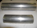
So, the exhaust has been on my mind for awhile. In the pics the exhaust looks closer then it really to the xmission lines. But never the less they were still a little closer then I wanted them to be. While there has been plans from the start to wrap the xmission lines I still felt that it was time to address the situation further.

So, I had a friend of mine that has built plenty of custom trucks (in fact he just got his 20year project done, here is a link: http://unserclosecustoms.com/index.php) come over and give my a direction to correct the problem. It was decided to build heat shields and ceramic coat the exhaust.
The hardest part of this was cutting up a perfectly good exhaust system. Here comes the wife with something to say about this!!!!
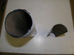
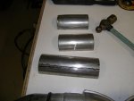
first thing first, all of the chassis needed to be covered for protection. I used some old fire resistant rags to help get the job done. Then came the cutting. I ended up cutting on the existing weld seams so that flanges May be added.


I used a flat magnet to hold the new flanges into place as I burned them in.


Here's a pic of the rear of the exhaust!

With all of the flanges tacked into place it was time to move to the heat shields!
So, I had a friend of mine that has built plenty of custom trucks (in fact he just got his 20year project done, here is a link: http://unserclosecustoms.com/index.php) come over and give my a direction to correct the problem. It was decided to build heat shields and ceramic coat the exhaust.
The hardest part of this was cutting up a perfectly good exhaust system. Here comes the wife with something to say about this!!!!
first thing first, all of the chassis needed to be covered for protection. I used some old fire resistant rags to help get the job done. Then came the cutting. I ended up cutting on the existing weld seams so that flanges May be added.
I used a flat magnet to hold the new flanges into place as I burned them in.
Here's a pic of the rear of the exhaust!
With all of the flanges tacked into place it was time to move to the heat shields!
Attachments
Last edited: