Ol' Yellar

Status
Not open for further replies.
Then the tappet chamber covers came off, no surprises there other than someone has used rtv to glue 'em on!
 

Attachments

  • Valve Tappet Chambers.jpg
    Valve Tappet Chambers.jpg
    132.5 KB · Views: 389
Ripped into the steering column next, the mast jacket has to go back to the paint shop now, the gearbox rebuild I can do anytime (within reason), the steering gear can be installed after the body is dropped back in place.

The steering wheel took quite a bit of finesse to remove in order to prevent any further damage. There are no chunks of the hard rubber cover missing, just a mass of cracks and voids.
 

Attachments

  • C1 Steering System 002.jpg
    C1 Steering System 002.jpg
    110 KB · Views: 366
Last edited:
The steering wheel will repaired using various epoxy materials after prepping all the cracks and voids.

Then a simple primer and finish paint work, most likely using the chassis enamel. I've done many similar wheel restos for antique boats, this one is not nearly as bad as those were.
 

Attachments

  • C1 Steering System 004.jpg
    C1 Steering System 004.jpg
    109.5 KB · Views: 366
Here's the steering partially dismantled. It's very simple ross cam and lever system, identical in execution (though not nearly as sophisticated) as the ross gears used in Scout 80 and some Scout 800, as well as pickalls over the years.

This one is filled with 140w gear lube introduced through a zerk fitting. Lotta cleanup to do here!
 

Attachments

  • C1 Steering System 006.jpg
    C1 Steering System 006.jpg
    148.1 KB · Views: 364
This shot shows the cam and shaft assembly removed from the mast jacket, along with the lever.
 

Attachments

  • C1 Steering System 008.jpg
    C1 Steering System 008.jpg
    120.3 KB · Views: 366
The mast jacket is swedged into the gland nut that holds it all together. At the top of the mast jacket is a simple linen/phenolic bushing.

This mast jacket sets the endplay of the cam/bearing assembly once it's all back together. Idea is to have that "vent" hole located on the bottom side of the column when locked down, just above the finisher that trims out the wooden toeboard. That helps keep any water that might enter the cab out of the column along with insects.
 

Attachments

  • C1 Steering System 009.jpg
    C1 Steering System 009.jpg
    81 KB · Views: 356
Pulled inspection on ed's bottom end today.

Some folks had "advised" me that these engines used poured babbit bearing systems for both rods and mains. My research had shown that to not be a fact, but rather an early form of insert bearings were used that May have also been shimmed similar to a poured babbit setup. And again, this conjecture has proven to be untrue.

While these bearings are not hardly state-of-the art for an insert bearing used today, they are inserts!

Here's a rod cap with plastigage crushed, this one shows to be just barely over the bearing-to-journal clearance spec of a max 0.0032". And the insert shows imbedded contamination which means it worked just as it should to prevent damage to the rod journal on the crank.

The markings on the steel backer of the insert tell me it's "standard" diameter, but that the rod inserts are not oem, who knows when they were replaced in the past,...but most likely when the cylinder block was bored.
 

Attachments

  • Rod bearing clearance.jpg
    Rod bearing clearance.jpg
    68.7 KB · Views: 319
Here's one of the main bearing caps. Again, this is an insert-type flat bearing which shows the same type of foreign material contamination.

Using plastigage on this one shows it's well out of the upper limit tolerance of 0.004".

This bearing has definitely been replaced at some point in the past, the backer shows an I.d. Which is marked 0.002" undersize. That was a common overhaul process to use when the crankshaft itself did measure a bit out of tolerance, but still had serviceable journal surfaces.

A typical "undersize" grind of the main journals would have been 0.020" under and undersize bearing inserts of the proper diameter would have been used.

These finding will be discussed with mikeee and we'll either bust down the motor and have the crank ground, or elect to simply roll in new rod and main inserts without tearing the crank out completely.
 

Attachments

  • Main bearing clearance.jpg
    Main bearing clearance.jpg
    108.9 KB · Views: 325
Quick update, lots of activity going on around here!

Ed's crank is out and it's in pretty poor condition, not undersize but the bearing surface is watermarked. It will grind out just fine.

I forgot to take my camera when I went by American spirit to drop off some parts, so the cell cam will have to do.

This is a shot of sections of the interior wood frame that has been reproduced in oak and installed.
 

Attachments

  • Ed New Wood1.jpg
    Ed New Wood1.jpg
    57 KB · Views: 298
Here's another shot, this is really nice work with accurate repops of the finger joints.

The top has been welded back in place now and the cab is in the finish out mode. All the repair metal work on the cab corner and the upper rear cab wall is completed. Looks like some sort of ladder rack (or antennas or lights???) had been mounted on the upper rear cab corners at some time in the past.

The fenders and other panels are in the paint booth for final prime.
 

Attachments

  • Ed New Wood2.jpg
    Ed New Wood2.jpg
    65 KB · Views: 296
All I know is, I would be more than glad to do this kinda work for free as long as I had a shack by the river and a levee or two.

I love seeing older builds and I've lately looked into what it would take to build a scaled-down inline flathead.

Needless to say, awesome post depicting what will end up as another rolling treasure.
 
Kyle,...my primary reason for documenting this resto is to simply show another side to what folks enjoy about the ihc heritage! Taking the entire range of products produced by IH from the beginning is simply astounding when compared to any another industrial entity! One more reason why we can't compare the IH product to any chryfordorlet product offering!

The "c" series trucks were far more advanced in design and technology as compared to similar offerings from other manufacturers of the era. In fact alot of what is seen in this rig was still being done on some IH platforms up through the end of the 60's.

Michael has many folks within his club that are following this documentation start to finish who really have no interest in the IH world at all, but do appreciate the process of bringing old iron back from the dead,...and ed is a superb example of a rig that was in amazing condition to begin with! If this ride was "typical" of what ya see for sale (total rot buckets with most of the engine missing) out there, the total nut on this resto could easily exceed $100k and that would not be for a show-quality rig!
 
Morning professor:
want to take a minute to thank you for doing a first rate job of documenting the "resurrection" of uncle ed. You're 100% correct about the following at this end of the world. Interest in the resto of rigs such as uncle ed is high on the list. That's why our club is called 'early iron'!!! Looking forward to my trip north to see first hand the goings on, frustrated that it won't be 'till next month. Gotta touch base with you and tracy, and feel the grease and smell the paint!. Will be bringing along some pretties from from grandpa earl to have replated at the same time those from ed get done. Mendomikee
 
Picked up the fresh flywheel/clutch combo from friction materials yesterday. See for yoreselves how nice their work is!

I had quite a long "how they do that" visit with three of the oldtimers who do the work there, the other two guys were busy! Each of these guys has a minimum of 25 years in doing this type work, the two guys who actual did ed's unit have both worked at this location for over 40 years!

Turns out, this clutch could be replicated if need be with off-the-shelf parts right there in the shop! It's no different at all from any current similar item, they use bulk parts to build whatever clutch cover is needed. They can even fab clutch discs from scratch if need be. The disc here is done in organic material, nothing fancy needed on ed!

This clutch cover assembly had been rebuilt some time in the past incorrectly it turns out. The wrong springs had been used and to compensate, the number of springs had been doubled up...which really doesn't "compensate"!

Once these parts are cleaned and ready for assembly, they are sometimes painted, but in the case of ed, they knew that his clutch was not painted on the oem side.

I had budgeted $275 for this work which is certainly ballpark for dealing with unobtanium...total nut including the flywheel grind was $135!!! So now...mendomikee is ahead of the budget on my end!
 

Attachments

  • C 1 Clutch & Flywheel 001.jpg
    C 1 Clutch & Flywheel 001.jpg
    63.4 KB · Views: 324
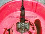
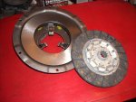
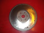
Here's ed's flywheel. This unit will install in only one position on the crankshaft hub in order to maintain balance.

The friction materials shop guys say this flywheel could be faced for the next hundred years if need be based upon thickness, they just simply compensate for material removal by refreshing the clutch cover and disc.

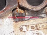
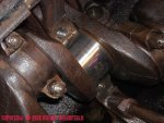
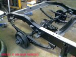
Once the flywheel was clean, we could actually see the three distinct wear points on the ring gear, I've marked those in the pic, they are spread around the circumference in nearly equal segments.

Here's the deal, something I've never had explained to me by a pro!:

when any four stroke/multi-cylinder engine is "stopped", due to the continuing cycling as it rolls down (the flywheel effect), it will always stop (in regards to an inline six cylinder motor) at one of three distinct points in relation to the starter drive system. In ed's case, that has been going on since 1934,...so do the math!

So in essence, only three segments of the ring gear receive all the luv when the starter is engaged each time! The rest of the ring gear is virtually virgin in condition!

This particular ring gear is simply pressed into a counterbore on the flywheel periphery. It is not "shrunk" in place as many are, and neither is it tack-welded as many ring gears are found on other flywheels.

So, this one will get a witness Mark on it, then the ring gear will be removed carefully with a big azz hammer/punch. Then it's position will be shifted approximately 20* and re-installed with the same tooling. Maybe I'll save this job for mendomikee when he comes up for a checkout in the next few weeks, he luvs to beat on shit with a hammer!
 

Attachments

  • C 1 Clutch & Flywheel 003.jpg
    C 1 Clutch & Flywheel 003.jpg
    53 KB · Views: 340
Sweet!!! At this rate, uncle ed will be ready and roaring in time for Binder Bee 2010. Who knows, I May drive up to the bee in grandpa earl and enter him, again, along with uncle ed. Only thing left for me to do is to find a real "pretty" while I'm at the show. Then invite her to drive one of my riggs back down to northern CA. After the show.

I'm down here taken shiney stuff off of grandpa to bring up with me and have it plated at the same time ed's stuff is done. Yep, stuff like this is "cheaper" by the dozen. Hopefully this will complete the resurrection of grandpa earl. Michael, keep on keeping on,... Mendomikee
 
Finally located a main and rod bearing set that will work, so the crank is at southworth's now gittin' done.

Dropped off the rest of the front axle schnizz at American spirit Tuesday, here's an update on some of the work.

First off, the wheels are back from the powdercoat operation and turned out the best I've ever seen regarding rotten wires! The contractor did a bang-up job of stripping all the old shit to bare metal with no slag. Tracy even managed to salvage the original rim bands!

The color is not a full-on gloss like the body will be, and not the true "chassis black" of the undercarriage. Somewhat in between and is what I deem absolutely the same tone as an oem wheel.
 

Attachments

  • Powdercoat Wheels.jpg
    Powdercoat Wheels.jpg
    83 KB · Views: 291
Last edited:
Here's the partially assembled front axle complete with shocks. I delivered the spindle sets so they can be installed "loosely" with no lubricant, once I get the brake situation worked out, they will be removed for lubrication and then final assembly.

The chassis needs to be mobile now so that it can go outside for final washdown and masking, then the body components will be set back in place for final blocking. Once that's done, the body pieces will go on bucks in the paint booth for color coat after mikee approves the final body work on the 22nd.
 

Attachments

  • Front Axle Partial.jpg
    Front Axle Partial.jpg
    68.7 KB · Views: 285
The completely reconditioned rear axle is installed now also, even though the brakes system installed will be tossed.

Disregard the "color", that is sanding dust...this is a body shop!

Also, some correct canvas insulator material has been trial fit to the frame rail that will be sandwiched between the running board skirts, the fenders and the body itself.

How about them overloads? Just like a modern peekup!
 

Attachments

  • Rear Axle Partial.jpg
    Rear Axle Partial.jpg
    77.8 KB · Views: 286
Status
Not open for further replies.
Back
Top