Ol' Yellar

Status
Not open for further replies.
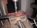
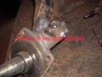
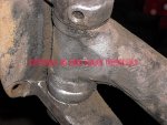
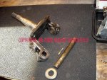
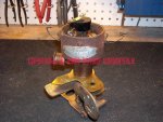
But gittin' the steering arms out was a bitch...had to rig the bigazz puller to split 'em. This one can make about 10 tons of pressure. The puller alone would not do the job...so I used the gas axe to spot heat the tapered boss while pressure was applied. Once critical mass was reached, it popped apart on it's own....repeat again on the other side.
 

Attachments

  • Bigazz Puller.jpg
    Bigazz Puller.jpg
    93 KB · Views: 543
Next, the spindles need to come off for inspection.

First ya drill a hole in the welch plugs in the top and bottom which protect the kingpin from exposure to road crap and retain grease.

Then I ran a sheetmetal bolt into each hole and out pops a welch plug. Plain old 7/8" items I keep on the shelf.
 

Attachments

  • Kingpin Welch Plug.jpg
    Kingpin Welch Plug.jpg
    102.2 KB · Views: 549
All kinds of methods are used on retaining kingpins on this type axle/spindle combo. Every oem used some variations.

This particular axle uses a straight pin that engages a corresponding slot in the kingpin itself to lock it in place. The pin was staked at four points on each side of the axle....pretty simple. So to remove, ya just use the proper diameter pin punch and drive the pin out and set aside.
 

Attachments

  • Kingpin Lockpin.jpg
    Kingpin Lockpin.jpg
    107.5 KB · Views: 538
Here's the entire spindle assembly laid out.

The timken lower thrust bearing is in outstanding condition and does not need to be replaced, it was loaded with grease (received through the one grease fitting which also loads the kingpin bushings).

The kingpin itself has no measurable wear, only the shiny surface where the bushings engage.

Likewise for the upper and lower kingpin bushings in the spindle, no wear!

So all this stuff gets cleaned, reassembled with pre-lube, and returned to American spirit for final paint.
 

Attachments

  • Spindle and Kingpin Assly.jpg
    Spindle and Kingpin Assly.jpg
    168.6 KB · Views: 541
Bouncin' around here trying to get all the sub-assemblies accounted for and parts list updated so I can chase stuff.

Here's the delco distributor (vacuum advance can was previously removed). Looks fairly decent at this point, but needs a heavy dose of cleanup once it's in pieces.

There are those that blow smoke regarding "the vacuum advance is a smog modification"...wrong! The vacuum advance (along with internal mechanical/centrifugal advance) was introduced to eliminate the need for a lever on the steering column to retard the "spark" for starting purposes. Once the engine was running and warmed up, then the spark lever was "advanced"...many motorcycles up into the 50's used that same type of ignition control system.

The vacuum advance unit did away with the need for a manual activation spark control. The ignition timing could be retarded to allow ease of starting by both hand-crank and electric,...it prevents starter drive damage from "kickback". The vacuum advance is controlled from a signal from a "ported" or "timed" vacuum feed on the carburetor body...same as is done today. That means the vacuum is taken from a point in the venturi above the throttle plate, that vacuum level changes with throttle plate angle (in other words..."engine load/vacuum").
 

Attachments

  • C1 Delco Distributor Teardown 003.jpg
    C1 Delco Distributor Teardown 003.jpg
    88.9 KB · Views: 518
Here's the distributor in pieces...not so good.

The plug wires had several terminals that were never crimped in the cap towers when the cables were fabbed! Thus the terminals stayed in the cap. These cables go in the scrap pile and more appropriate appearing (but modern) cables will be installed later.

All the treated paper insulators in the breaker point system were rotten and mostly jury-rigged.

The breaker point and it's companion fixed point cab be seen to be fried. Notice how the insulated point contact has turned blue?? That is caused by not using the correct ignition coil...and leaving the ignition switch "on" without the engine running.

This rig was half-assed converted to a 12vdc system. The starter is still a 6vdc setup, which makes it spin like a bitch! That's ok, starters are intermittent use and can handle 12vdc until they fry (probably never).

But the ignition coil installed was some boneyard 12vdc part for a Ford v8 with a totally incorrect primary resistance factor for a six cylinder ignition system. It's now in the trash can somewhere.

The biggest problem...someone has shimmed under the distributor advance plate brazed to the drive shaft...that raises the mechanical advance to where it drags heavily on the breaker plate. To combat that, someone has used a hammer to "relieve" the bottom of breaker plate which means it's not even close to flat! And ya can see in the pic, it still rubs/makes hard contact.

So the distributor itself needs much luv, but it's certainly repairable.
 

Attachments

  • C1 Delco Distributor Teardown 007.jpg
    C1 Delco Distributor Teardown 007.jpg
    133.3 KB · Views: 543
Interesting distributor...

I have never seen distributor weights with "pins" on the end. Looks like they rubbed on the plate...

Otherwise, they could pass for corvair (or Chevy 6 cyl) delco distributor weights.

I assume you checked the weight pins on the distributor plate for wear?

The "pin hole" on one of the weights ("top") looks worn -- but it could "photo perspective".

Good luck, it will take some "work" to get that distributor ship-shape...
 
After looking at the pics following your various tear downs, it is amazing that uncle ed chugged around your neighborhood as well as he did. Amazing. And virtually no leaks on your shop floor. With a higher rear end it seems within reason to anticipate a 55 mph cruising speed. The conversion from mechanical to juice brakes will eliminate the need for me to travel around with a rope tied to bolder stored in the bed!!!
 
interesting distributor...

I have never seen distributor weights with "pins" on the end. Looks like they rubbed on the plate...

Otherwise, they could pass for corvair (or Chevy 6 cyl) delco distributor weights.

I assume you checked the weight pins on the distributor plate for wear?

The "pin hole" on one of the weights ("top") looks worn -- but it could "photo perspective".

Good luck, it will take some "work" to get that distributor ship-shape...

The pins on the ends of the counterweights are actually "limit" stops, they engage the two hole on the plate brazed to the driveshaft. Nothing in the advance mechanism is worn or damaged other than someone has jacked with the springs, one of which is making contact with the breaker plate

all the problem areas will be addressed during overhaul, gonna take some bending and tweeking to line everything up again. This is typical of what ya find when someone has been into a distributor (or carburetor) who should not have been allowed to have driver's license.

All this will make sense when ya see the distributor rebuild pics.

Actually if ya flop the advance unit over and mount to the top of the shaft Robert, it's near identical in actual construction to the delco sparkers you are familiar with other than the size. This same distributor body was used on some early motorcycles also that had battery ignition (not a mag).

I "think" this distributor was used on all the IH four and six banger stuff up until the end of the flathead production (1949??). The later sixes used a very similar unit (same kind of "rotating distributor" vacuum advance), but they were about two times the size overall.
 
Real similar to the early Ford stuff with one exception the king pin retainer. Early Ford has a tapered locking pin that is pulled in with a lock nut and can not fall out. Do you think it is prudent to ream the axle to except a standard threaded taper pin and a nut? I would be a bit nervous.

Could us a taper pin 1/2" per foot hand reamer and creat the taper in the king pin boss then install the correct standard 1/2" per foot an taper pin locked in using the nut.
A few pix of early Ford stuff and an an taper pin sheet from aircraft spruce.

8147d1261960336-ol-yellar-p1000125-large-.jpg

Typicall 32 Ford with 4" drop

8149d1261961269-ol-yellar-an386.jpg


An386 pin detail for more detail see attached pdf
 

Attachments

  • 0101ct_kingpin_01_z.jpg
    0101ct_kingpin_01_z.jpg
    25.4 KB · Views: 366
  • P1000125 (Large).jpg
    P1000125 (Large).jpg
    86.8 KB · Views: 735
  • an386.pdf
    116.9 KB · Views: 617
  • an386.jpg
    an386.jpg
    42.7 KB · Views: 717
Last edited:
Thanks for the info Robert! I was actually looking for something similar the other day for a different project!

I think this rudimentary lockpins will be fine for another many years once they're re-installed with loctite. It has four equi-distant punch divots to peen the outer edge of the holes over the head of the pin on each side of the axle eye, on each side. While the pins were not rusted in place, it took considerable force to drive em' out. And the welch plugs, once set are insurance also, in addition to containing grease-ooze.

I had to really dig to find the pins in the first place...my initial thoughts were that the kingpins were a press-fit in the axle ends. But I spent quite a bit of time researching kingpin retention methods before this one popped out. I didn't want to waste time digging for the pins through all the muck, but in the end I had no choice.

Here's all the front axle iron laid out. The tie rod ends and their mating balls are in perfect condition, just need cleanup and pre-lube to reassemble once cleaned.

I've tested all four lever-type hydraulic shocks and they are functional also as well as their links. So all this stuff goes somewhere tomorrow, either to the acid dip or the sandblaster, tracy will make that call (of course, the shocks won't be dipped!). Once it's all clean, then I'll retrieve and re-assemble, then the stuff goes back to American spirit for painting and hanging back on the frame.
 

Attachments

  • Axle pieces 002.jpg
    Axle pieces 002.jpg
    140.2 KB · Views: 412
Here's the 9" clutch cover and disc. Nothing unusual here, looks just like a modern clutch.

This stuff is going to the rebuilder in town probably tomorrow, I want them to give me a second opinion on the pressure plate to make sure I'm not missing anything, but it sure looks good to me.

The flywheel will be dropped at the machine shop just a few blocks away for a re-surface.

The pilot bearing is a standard shielded one side bearing as used in many later IH apps.
 

Attachments

  • Nine Inch Clutch.jpg
    Nine Inch Clutch.jpg
    130.4 KB · Views: 449
Here's the timing grid which in this case is stamped on the flywheel. Since the flywheel can only go back on the crank hub in one position, ya can't "stab" it incorrectly!

The actual stationary timing tick Mark is on the bellhousing adjacent to the starter, has a small drop-down flap/cover to keep critters (and fingers) out of the hole when the motor is runnin'.
 

Attachments

  • Timing Grid.jpg
    Timing Grid.jpg
    75.1 KB · Views: 463
Figured you'd feel they were ok and they probably are with the welch plugs also keep'n them in place. If the king pin fits tight in the axle like in a snug slip fit you are probably ok but if the king pin has some wiggle room in the axle the keeper pin can be hammered loose. I've unfortunatly seen it happen on early Ford shit where the owner refused to do a basic recheck of fasteners after building a car.:incazzato: well lal (live and learn) or not and learn :icon_xd:

this is common in anglia spindles like is on the f/c. Only set screws clamp the king pin so we check them often and even add a second one for insurance.

Looks like a cool project michael. The roots of it all for damb sure. I'm enjoy'n watch'n the build.
 
Last edited:
after looking at the pics following your various tear downs, it is amazing that uncle ed chugged around your neighborhood as well as he did. Amazing. And virtually no leaks on your shop floor. With a higher rear end it seems within reason to anticipate a 55 mph cruising speed. The conversion from mechanical to juice brakes will eliminate the need for me to travel around with a rope tied to bolder stored in the bed!!!

Hey micheals g&m well it looks like mr.g will finally have a vehicle that will keep up with others even if a grappling hook is a needed accessory. But in all seriousness looking at those backing plates couldn't you mount the hydrualic cylinder to it and modify current setup to work as hydrualic system, a couple of holes and a little enginuity can go a long ways. If that doesnt work or rare parts cant be found I donate the hook to the cuase.
 
the pins on the ends of the counterweights are actually "limit" stops, they engage the two hole on the plate brazed to the driveshaft. Nothing in the advance mechanism is worn or damaged other than someone has jacked with the springs, one of which is making contact with the breaker plate

all this will make sense when ya see the distributor rebuild pics.

Ok, I understand now...

I was putting the distributor back together incorrectly (weights "pin up") -- never done that before:shocked: :icon_rolleyes:

the corvairs have a "pin" on the bottom of the distributor cam that "engages" a hole in the dist plate... Performs the same "function" I would think.

Wonder if the distributor springs have been replaced with newer / "modern" springs?
 
hey micheals g&m well it looks like mr.g will finally have a vehicle that will keep up with others even if a grappling hook is a needed accessory. But in all seriousness looking at those backing plates couldn't you mount the hydrualic cylinder to it and modify current setup to work as hydrualic system, a couple of holes and a little enginuity can go a long ways. If that doesnt work or rare parts cant be found I donate the hook to the cuase.

I've looked into converting the mechanical brake backing plate to hydraulic extensively! In fact, I laid out one scenario yesterday on a mechanical backing plate but it's no-go. Simply won't work as there is absolutely now way to install a shoe anchor and a hydraulic cylinder in the space provided by the reinforcement.

There are many 12" brake systems that May be adaptable, the major hurdle is the offset in the drum itself (along with the offset built into the backing plate) needed to allow the original wire wheels to mount, these are completely unlike conventional disc wheels. But I do have a very effective workaround for that available. And modding the backing plate centers is certainly not a big deal to allow mounting on the spindles and the rear axle housing flanges.
 
figured you'd feel they were ok and they probably are with the welch plugs also keep'n them in place. If the king pin fits tight in the axle like in a snug slip fit you are probably ok but if the king pin has some wiggle room in the axle the keeper pin can be hammered loose. I've unfortunatly seen it happen on early Ford shit where the owner refused to do a basic recheck of fasteners after building a car.:incazzato: well lal (live and learn) or not and learn :icon_xd:

this is common in anglia spindles like is on the f/c. Only set screws clamp the king pin so we check them often and even add a second one for insurance.

Looks like a cool project michael. The roots of it all for damb sure. I'm enjoy'n watch'n the build.

I too have experienced the "loose kingpin disease" when dealing with similar shit in the old days! That's why I was very surprised to find only a straight lockpin staked in place! Especially when the rest of the suspension stuff is major overkill (and hi-tek!) for the era!!

Once I got the axle ends cleaned better yesterday, I could then see why the welch plugs were a bitch to remove...they had also been staked in place using what appeared to be some tooling in a drop-hammer...obviously not done with a hammer and chisel! So that sez this whole setup is original!! To think that the kingpins/bushings/thrust bearings have survived all this time in perfect condition is truly amazing to me!

Next up project-wise is Todd and I doing the kingpin job on his '66 Ford with the hotted-up fe motor. It's in terrible shape and eatin' tires...so I know it's all rotten. It's really gonna be a bitch to do compared to the c-1!
 
More bounce-around, gotta git this stuff prepped for return to American spirit for painting asap.

Bumpers on the c-series trucks were an option, along with many other items, including three different size/types of wheels.

This rig has bumpers front and rear, both in excellent condition and just need a re-plate.

The front bumper mount is actually a rudimentary leaf spring. Shit man, this one would pass as a late-model dot/nhtsa "5mph" bumper and it's the right height also!

Obviously the bumper was used to absorb a shock sometime in the past, one of the holes drilled for a frame mounting point cracked through. Then someone laid a patch over one side to piece it together. Not very esthetically pleasing and of course the bumper won't align properly in the end.

Gotta fix this.

Appears the patch was laid on using hi-nickel arc rod, so that will be easy to cut back using the gizz wheel and gas axe.
 

Attachments

  • Butchered Bumper Spring.jpg
    Butchered Bumper Spring.jpg
    101.7 KB · Views: 415
So I drilled the hole oversize to accept a steel bushing. That bushing will be burned in with mig and left proud for final finish grind.
 

Attachments

  • Drilled for Bushing Insert.jpg
    Drilled for Bushing Insert.jpg
    62.3 KB · Views: 396
This is the back of the bumper spring with the area to weld after prep work.

The actual crack has been vee'd out to drop in a mig bead. The bushing will be stitched to the chamfered hole.

Once the back of the spring is securely stitched up, then it'll get flopped and the ugleeazz patch ground off. Then the crack will be vee'd from the front and the welding scheme repeated.

Once both sides are ground flat and the edge contour is re-established, then the hole will be drilled slightly to final size.

These point line up directly with the ends of the frame horns which are boxed construction. One side had a bolt in it, the other side had a stud with nut. The holes in the frame horns are tapped, so we'll use appropriate hardware in this location once I figgr out if a bolt or a stud was oem.
 

Attachments

  • Prep for Initial Welding.jpg
    Prep for Initial Welding.jpg
    72.8 KB · Views: 421
Welded up the bushing and crack on the front side . That allowed me to gizwheel the patch plate off without the spring falling into two parts.
 

Attachments

  • Bumper Spring Repair2 001.jpg
    Bumper Spring Repair2 001.jpg
    86 KB · Views: 359
The cracks and bushing are sticthed in on the backside, needs some grind-time spent on dressing everything.
 

Attachments

  • Bumper Spring Repair2 004.jpg
    Bumper Spring Repair2 004.jpg
    127.1 KB · Views: 361
The finished product, rough-primered and ready to go back to American spirit.

Check this off the list.
 

Attachments

  • Bumper Spring Repair2 006.jpg
    Bumper Spring Repair2 006.jpg
    46.2 KB · Views: 356
Mikee just sent me this link...any of ya interested in dealin' in old junkiron, this website is a great history lesson just for the pics of what a real auto parts looked like back in the day!

I can well remember near identical parts houses all over the southwest where I'd hang out while travelin' with pop (the original rodelizrd) as he made sales calls in every propane, hardware, furniture, co-op, and appliance store in any burg that had one. And my favorites were the goodyear stores, western auto, and whites auto where all the stuff they had was laid out in bins mounted on the gondolas...if ya wanted help findin' a whachamafitzit for a '27 studebaker they'd help if ya asked, otherwise it was self-serve and heaven!

kisber enterprises > home
 
Status
Not open for further replies.
Back
Top