

You are using an out of date browser. It may not display this or other websites correctly.
You should upgrade or use an alternative browser.
You should upgrade or use an alternative browser.
Limited disassembly of a 1980 IC 196
- Thread starter Mark Pietz
- Start date
Mark Pietz
Member
Turbos arrived yesterday. They appear to be every bit as nice as promised. Since I am turning one of them into a TRW/Rayjay "F/B" (F flow compressor/B flow turbine), I need the "B" turbine and matching exhaust housing. The turbine should be arriving Monday, and wonder of wonders, the "junk" housing I've been using for mocking up distances turns out to be one, and not an F housing as I had believed. For those wondering about this F/B business, it is where one can mix-and-match certain compressors and turbines. The modern version of this trick is the very common T4/T3 turbo, where a larger compressor is mated with a smaller turbine to spool up quicker. Corvair people were doing this in the '60s! In my case the F compressor has proven to give the correct flow for the slow-turning 196.
I took a quick measurement of the wall thickness of the compressor's inlet. Outer diameter is 3", and it is tapered inward down to the diameter of the compressor's blades. If I have the excess length cut off, say, to 1/4" or so to where the blades begin, it looks like I would have a circular mounting pad about 0.625" wide. That should be enough width for 5/16" mounting bolts used in any intake flange I fashion.
About where to put the intake. For now my goal is to configure placing the carb or throttle body in the vicinity to the right of the PB booster. It looks feasible at this point to be able to use a stock IH air cleaner in this area (if Hamilton EFI) although it would be tight. This would also allow retention of the snorkel hot air hose, snaking around to the hot air stove. Another option would do a variation on the air cleaner I used for my first turbo iteration. That was grafting an IH snorkel, with air valve, to a Corvair turbo air cleaner, turning it around so that the snorkel is centered to the rearmost portion of the firewall and against it, cutting a hole so that air comes in from the cowl area. I had already considered something like this but really don't want to hack up the firewall unless it is necessary or beneficial. I could then run a hose from the air cleaner to a hat on the carb or TB. I am seeing that early Corvair turbo air cleaners are still out there. I prefer the early version that isn't chromed since my snorkel isn't chromed. These air cleaners are compact, versatile, and obviously provide adequate air flow.
Mark Pietz
Member
Robert,
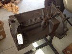
Looking for an answer to an earlier question so I don't have to go to the difficulty of dropping a pan to clean out debris from drilling holes in the FP boss, if I break through. I snagged this pic from your thread. From what I can tell, it looks like there is a lot of meat to either side of the main hole. Are these tapped holes blind? Are these holes blind?. If I can tap 1" of threads, I should be good to go. Once I get the holes tapped, I can fab a mounting bracket for the turbo and begin to fit things up. The vehicle won't have to be undriveable while I do this.
Looking for an answer to an earlier question so I don't have to go to the difficulty of dropping a pan to clean out debris from drilling holes in the FP boss, if I break through. I snagged this pic from your thread. From what I can tell, it looks like there is a lot of meat to either side of the main hole. Are these tapped holes blind? Are these holes blind?. If I can tap 1" of threads, I should be good to go. Once I get the holes tapped, I can fab a mounting bracket for the turbo and begin to fit things up. The vehicle won't have to be undriveable while I do this.
Attachments
Robert Kenney
Super Moderator
I just saw your post. Let me check.
Robert Kenney
Super Moderator
The full length of the casting from the machined pump mounting pad is 1", the factory 3/8 nc threaded holes are .85 deep
Mark Pietz
Member
Had a brain fart thinking those might have been 5/16" bolts. 3/8" bolts are better to secure a bracket, in any case. Thanks again for checking. Today my B flow turbine arrived, so I will have a conversion to do after the Holidays.
Robert Kenney
Super Moderator
Had a brain fart thinking those might have been 5/16" bolts. 3/8" bolts are better to secure a bracket, in any case. Thanks again for checking. Today my B flow turbine arrived, so I will have a conversion to do after the Holidays.
Depending on which side you're on, fortunately it was a brain fart, but not yours, mine. They are 5/16 NC not 3/8. .257 tap drill size.

Mark Pietz
Member
Doesn't really matter who farted, as long as the air is clear enough to see that it's a 5/16" before I start drilling.
Mark Pietz
Member
It's a new year and progress resumes....slowly. I need to take care in drilling and tapping those two holes. I don't have the skill or confidence to do it "free hand" so I decided to make a jig from a block-off plate, assuming I can pilot off the holes in the plate. Towards this end I got a plate that fits a Mopar 383/440, since the Felpro gasket number is the same for it as for the SV. The holes in this are 7/16", and I have drill bushings on order from McMaster-Carr with an OD of 7/16" and an ID of 0.257, and 5/8" high. Pressing those bushings into these holes creates a jig of sorts that I will lightly epoxy onto the unfinished surface of that boss so it doesn't shift. Using a F letter bit is just right to drilling and then tapping for 5/16" thread. Chisel off the plate and I have a mounting surface to bolt to.
Attachments
Mark Pietz
Member
I hear you, but here's the deal. I don't really have that much wiggle room for the drilled holes to be out of line or off center, or the bit not entering the boss's surface "square". I do not trust my skills to punch two dimples and drill them free hand with the engine still in the vehicle. And one edge of the boss has a casting defect (judging from the casting I think they weren't too particular at that time because the fuel pumps had long since been moved to the front) that makes getting it right even more important. Drill bushings set square to the surface will ensure the F drill goes in as straight as possible. You know, a transfer punch set was one of those things I never got around to buying. Probably too old now to justify. ")
Robert Kenney
Super Moderator
100% agree, Drill bushings are super handy if you only have one shot to get it right. It's the worst to have a threaded hole at a slight angle and while torqueing the bolt head pops off.I hear you, but here's the deal. I don't really have that much wiggle room for the drilled holes to be out of line or off center, or the bit not entering the boss's surface "square". I do not trust my skills to punch two dimples and drill them free hand with the engine still in the vehicle. And one edge of the boss has a casting defect (judging from the casting I think they weren't too particular at that time because the fuel pumps had long since been moved to the front) that makes getting it right even more important. Drill bushings set square to the surface will ensure the F drill goes in as straight as possible. You know, a transfer punch set was one of those things I never got around to buying. Probably too old now to justify.
Mark Pietz
Member
My great fear summed up!100% agree, Drill bushings are super handy if you only have one shot to get it right. It's the worst to have a threaded hole at a slight angle and while torqueing the bolt head pops off.
Today a friend in the Corvair world found a short section of exhaust tubing with the unique flange that holds the donut packing against the housing. On its way to put in the pile of bits needed to start an exhaust system. I can weld a tight elbow to this as I did in my first iteration. Yay!
Mark Pietz
Member
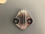
Progress has been frustratingly slow. My need to drill/tap the 5/16" holes in the FP boss have stalled due to a McMaster-Carr backorder on the specific drill bushings (for an F bit). The bit arrived, but the bushings are still over a week out! In the meantime, I ordered a special adapter for a T4 turbo base-to-2.5" V-clamp. I had some spare 2.5" V clamp pieces from my earlier iteration, but when the adapter arrived last night, I discovered those pieces weren't compatible with the adapter. Here is a pic. I think 2.5" is a bit big for the pipe from the exhaust manifold to the turbo, so I plan on reducing it to the nominal 2 1/4" that IH used as for the down pipe. This should keep the exhaust velocity up. When getting the turbo exhaust elbow (pictured previously) I overlooked ordering the triangular mounting collar that holds the pipe and donut packing against the turbine housing outlet. One is now on order, as are a couple of packings. These should arrive within the week. Because I am curious about what horsepower my engine is currently producing, I decided to revisit the "poor man's dyno" application on my iPhone. The Dynolicious app is now defunct, so yesterday I downloaded a popular app called "PerfExpert". Haven't had time to actually makes some runs, but it looks like a good place to get a decent approximation of rear wheel horsepower. This app appears more sophisticated than Dynolicious, as it measures hp from a rolling start and using 2nd gear to max rpm, then coasting down. One inputs a guesstimate of Cd (a Scout II is like pushing a billboard through the air). I come up with a rough frontal surface area of 3.345 square meters. So we'll see. Maybe have some numbers to report this weekend. Also towards moving my project along is that I bought a new Argon/CO2 bottle for my mig. I was careless and overlooked moving the one I had when I had a chance to move heavy goods to Texas. Beakins wouldn't move it, of course, so I gave it to a neighbor working on his car project. No time to look back, just ahead!

Robert Kenney
Super Moderator
I don't think 2-1/2" is to big for the hp you are likely to produce.
Nice when you can buy a semi custom part and not have to make it..

Nice when you can buy a semi custom part and not have to make it..
Mark Pietz
Member
I think fabricating the new exhaust system will be much easier than the last. I am envisioning a relatively simple swoop down, turning towards the rear, and essentially running under the clutch relay shaft and straight back to the muffler. I will need to clearance the front motor mount to clear the pipe stub pictured, but have a plan for that. Will sketch that out and post later for comment. I am hoping to greatly improve my welding skills in this exercise.I don't think 2-1/2" is to big for the hp you are likely to produce.
Nice when you can buy a semi custom part and not have to make it..
Mark Pietz
Member
Robert,
Here are some cheery numbers! This morning I was playing with the PerfExpert dyno app. Found a flat, country road with a decent, level, smooth surface, and made some runs. The thing with the app is that one enters a lot of parameters, and via GPS it adds in local meteorologic data, and then one does a very soft launch in 1st gear, just enough to get rolling and then shift into 2nd, still under 2,000 rpm (I don't have a tac but am sure I was under), then you punch it and run it up to redline, then coast. With my gearing and tire size I calculated that to be around 4,000 rpm @ 40 mph. We know how accurate the speedos are on these things. So when I hit 40 the engine was screaming, I let up and coasted. Here are the rough numbers; I say rough because I still need to find a local public scale to zero in my running weight with a full tank of gas. I am using earlier numbers that I'm sure are reasonably close. This is with stock ignition and settings, full smog gear (EGR disabled) and cat. On one of the runs I hit over 4,600 rpm before letting up! Good thing I replaced all the springs (Jeff had a stash of OEM springs) when I did the rebuild! Float would be a very bad thing.
Flywheel: 100 hp @ 4,051 rpm; 165 ft-lbs torque @ 2,024 rpm
Rear Wheel: 85 hp @ 4,051 rpm; 140 ft-lbs. @ 2,024 rpm
Published data is 103 hp @ 4,000 rpm / 176 ft-lbs torque @ 2,000 rpm. Assuming that is a fresh engine with an ideal "tune", on a dyno, with accessories, that isn't too bad!
Observations: I liked the Dynolicious app but never got a chance to really use it properly, and in any case it is now defunct. The runs I made with it were at an elevation around 1,200 feet, and getting clean runs was dicey because of the iPhone mount. Lot of vibration and false starts. This is easier, and I taped the iPhone to the surface of the transmission cover, right behind the shift lever. No vibration there! Today is humid (when isn't Houston...) and elevation is around 100 feet. Next step is to verify the weights and make and average a number of runs to establish a decent baseline. A concern I have is after I get the turbo installed. Power will be measured with whatever boost I am generating half-way through the pull in 2nd gear. As we know, boost is a funny animal and depends on gearing and load. The app has a "timed run" option for generating numbers, and I'll have to delve into that to see how it works. If it is timed over a known distance, then I should be able to generate more realistic numbers once I pull boost in 3rd or 4th. From previous experience, that is when the engine began to sing!
Last edited:
Robert Kenney
Super Moderator
Comped for altitude, 1200ft above sea level, you made 104.5hp at the crank. That's pretty accurate!
Mark Pietz
Member
Right. The rule of thumb is 3% per 1,000 feet elevation. I've been in communication with the people that designed the app. I think they are European, specifically French. A critique I had was that one enters tire size from a list. Metric, of course, and I had to choose the metric tire closest to what I run, which is a 31 x 10.50 x 15. The choice was 265x75x15. I pointed out that there is a huge number of trucks and SUVs that run tires like mine, so I gave him a short list of common sizes from 30" up to 33". He seemed receptive. There is a timed run option, but I still haven't gotten clarity on how the 1/4 mile is determined. I was hoping GPS. Anyway, we'll see. Two days ago I had a setback. I ordered a matching V-clamp assembly for that T4-v-band adapter. The welding warped the half on the adaptor and made it 0.100" out of round, almost a slight ellipse. No go to mate up, so I sent it back. Bummer. That was a nice weldment! I've located another vendor that has a T4-V-2 1/4" V-band in the same configuration, but in cast stainless steel, with a complete V-band assembly. What's your opinion of a cast part? Another option is that I found a 1/4" thick T4 flange with a hole machined in the center, also for 2 1/4". Although not ideal, do you think I can adequately weld either a SS stub (or even mild) using my mig with Ar/CO2? Bottles are pricey and I just bought one, and don't feel motivated to buy another just for this.Comped for altitude, 1200ft above sea level, you made 104.5hp at the crank. That's pretty accurate!
Robert Kenney
Super Moderator
I like cast stainless more that the traditional cast iron. The SS is pretty much like cast steel in grain structure. For welding you're using er70 or similar wire in the MIG? Either way you will be fine with the standard mild steel argon/co2 mix.