You are using an out of date browser. It may not display this or other websites correctly.
You should upgrade or use an alternative browser.
You should upgrade or use an alternative browser.
Engine Cooling Systems and Components
- Thread starter Michael Mayben
- Start date
Craig
Active member
Looking good lou. I have 3 feel-pro gaskets sitting on the shelf and your welcome to one. I can even bring it by, good excuse to see what your up too 
I took my ornament and bent the stamped steel impellers up and it worked better. My brother has access to a digital flow gauge he uses at work. To bad he lives back east! I believe the holes also help get rid of cavitation on the back side of the impeller.
I took my ornament and bent the stamped steel impellers up and it worked better. My brother has access to a digital flow gauge he uses at work. To bad he lives back east! I believe the holes also help get rid of cavitation on the back side of the impeller.
Lou
Member
I'll have to study up on the purpose of the holes in the impeller. Here's a photo of a pump I used about 15 years ago and it had no holes. I'm sure I've read about this somewhere.
Craig, you're welcome to drop by, I'd love to hear your perspective and verify the thickness of a fel pro gasket. My thinking at this point is that as long as I can move the impeller on the shaft I can use any gasket I like. I'm inclined to stick to napa as I've already got some and can get them anywhere. I left my number on your phone Saturday, if don't have it, let me know and I'll pm you.
The new radiator should be here next week. Thanks Jeff!!!
Attachments
Last edited:

Lou
Member
I did a bit of reading on the purpose of impeller balance holes and the primary reason is to reduce/eliminate axial loads on the shaft bearing. So taking up gregs challenge I cut some 1/2" x 20 set screws in half and locktited them in place. Next I'll drill those out to the original size and dress the faces with a dremel. I think for setting up my spare pump I'll only drill out two holes!!
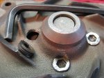
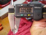
The stock gasket is .027". I set the pump up with the gasket, bolted it down and checked the clearance with a piece of solder, okie plasti gage. It comes in at .050 so I've got some playing to do. This sure beats my day job.
The stock gasket is .027". I set the pump up with the gasket, bolted it down and checked the clearance with a piece of solder, okie plasti gage. It comes in at .050 so I've got some playing to do. This sure beats my day job.
Attachments
Michael Mayben
IHPA Tech Moderator - Retired & No Longer Online
You must be either bored or now retired lou!
New pumps are dirt cheep...just verify vane clearance on 'em, adjust if needed, and go play!!!
New pumps are dirt cheep...just verify vane clearance on 'em, adjust if needed, and go play!!!
Lou
Member
I'm killin' time until Jeff calls with my new radiator Mike! I've determined that the only way to clearance these things it to move a cast impeller on the shaft or bend the vanes on a steel impeller. The pumps I'm working on are new, the spare I carry will be set up next. I don't see any other way to do this. The re-size of the balance holes of course is the present day manifestation of the flash backs I was promised in '67!!
Lou
Member
Ok, I've got this first pump clearance issue hammered!! This should work fine once my new radiator arrives next week. Meanwhile I'll work my newfound magic on the spare pump I'll get from Jeff. I think I'll try my new skills on a stamped steel one. Thank you guys for all the insights!!
Attachments
Michael Mayben
IHPA Tech Moderator - Retired & No Longer Online
I'm goin' right to the shop and modding all them pumps I got lou just like yorn! Hell man, that good for at least ten more ponies...and we''l just run the sumbitches on thermo-siphon which wuz guud enuff for a models!
Save them chunks of cast though, we May need 'em to melt down and use to mold some new water pump housings!
Save them chunks of cast though, we May need 'em to melt down and use to mold some new water pump housings!
Scoutboy74
Moderator
Dag nabbit lou! You musta got that nickel rod purdy hot!
Lou
Member
Mostly done with the pointless but enjoyable academics here. I used clay and solder to determine that the curve of the cast impeller does not match the volute. I set the outer tips of the impeller at about .020" with gasket installed and called it a day. The clearance gap at the center tips is probably about .035" greater. I pulled the hub .070" which leaves .530" of fit on the shaft. When I pick up the new radiator next week I'll get a stamped steel pump and set that up. I'm curious to see if the clearance is more even. One of these pumps will go on the truck and the other goes in the parts box.
Michael Mayben
IHPA Tech Moderator - Retired & No Longer Online
Witha stamped curkalator ya can kool tha motor and compress air at the same time lou if ya turn the impeller backwards on the shaft and start the motor in backwards mode too. I know you got that special-order double selectable rotation motor that was a factoree option only in the state of kowabunga....the 345 ba unit (bazzackwurds).
Onna more serious (but not completely) note...the vane-to-volute angle of the stamped impeller is an absolutely perfect match. Must be that's why they work really well...if the root manufacturer paid any attention at all to assembly specs when either rebuilding,...or manufacturing new water pumps for this shit. Cast impeller profiles are all over the place, some match, some don't, but then most are half eaten away nowadays so whatcha gonna do, weld up the vanes and regrind to some new "dyno-generated" profile?
Cast impeller pumps are gone from the marketplace though some pop up from time to time, so do nos cast impellers and water pump rebuild kits...but who cares??? The perpetuators of urban mythology in the world of IH???? Can ya gitta replacement stamped vane pump that's not assembled correctly??? Hail yes! That is why when ya take a part out of a box (any part)...ya look at it and assume it's fucked up...then ya do whatcha gotta do to make it work right. That is the difference inna mechanic anda "technician"/hobby-jockey! Iffa countermonkee asks..."would you like a cast or stamped impeller with that water pump body sir?", then ya could urban myth yore azz off all day long and enter into a debate/training session with that monkee who could care less about anything regarding pumps, impellers, or IH in general.
A stamped impeller pump is whatcha gonna git nowadays, just check impeller clearance and then deal with it somehow. Too bad folks don't spend more time dealing with real engine cooling issues like 80% restricted heads and water jackets (lack of maintenance), cooling systems which won't pass any kind of a pressure test (lack of proper maintenance/repair), missing fan shrouds, thermo-control fan clutches that won't lock up, etc.
Last edited:
Lou
Member
Mike yer killin’ me an I love it. When I bought these two pumps (installed & spare) I got a favor from my napa counter guy (that I’ve known since 1972) and he special ordered the gmb cast pump up from los angeles ‘cause that’s what I thought was true (pre mm & hylomar days). Now I’ll base my opinion on the curve of the two. I’m really waiting to see how the steel pump curve measures up to the volute. At some point I’ll be happy to mig (cast or steel) the face of the vanes for a perfect match to the volute at .020” or so with gasket and call it a day. It’s not really that big a deal and maybe I can sell one or two to those how know. I’ll work up a curve graph for the volute tomorrow and see how that compares to the curve of the impeller vanes. I’m assuming that the clearance should be the same along the length of the vane, that being the magical .015".
Lou
Member
Got bored this afternoon as I don't pick up my new radiator and pump until tomorrow. So, I threw four rs370 thermostats into a pan of boiling water. Three were 195deg and one was a 180deg. The water was 202deg. The three 195's opened a max of just under 3/16ths while the 180 opened to about 5/16ths, almost twice as far. Any thoughts as to how far the brass can is supposed to move away from the body of the thermostat?
Eric VanBuren
Member
One thing to remember is that the rating is the middle of the t-stats range. For example the "180" should start opening 170 +/- degrees and be fully open at 192+/- degrees. So the 195 wont be fully open until around 207 degrees. Sorry I don't have any data on the max travel but you can try again tomorrow with a little hotter water and see if the 195s will open to 5/16" if the water is staring to boil.
Craig
Active member
Lou which t-stat holder do you have. There is one with a 1" or so diameter hole in the middle and then there is the smaller version. We did some testing a while back. Boiled both the t-stats and the water neck which holds the t-stat looking to see how much of the by pass was blocked off. I.e checking the clearance around the bottom of the t-stat to the housing. We only used 180's so no data on the opening of 195 but I would assume they would be the same? The t-stat needs to close off the by-pass or your going to recycle water into the engine without going through the radiator. Duh. We did notice the by-pass was not completely block off. This lead to more testing with a napa t-stat we had on hand to see how it closed off the by-pass.
Sounds like your on the right track as the t-stat needs to open enough or your going to still have issues.
Sounds like your on the right track as the t-stat needs to open enough or your going to still have issues.
Craig
Active member
one thing to remember is that the rating is the middle of the t-stats range. For example the "180" should start opening 170 +/- degrees and be fully open at 192+/- degrees. So the 195 wont be fully open until around 207 degrees. Sorry I don't have any data on the max travel but you can try again tomorrow with a little hotter water and see if the 195s will open to 5/16" if the water is staring to boil.
Excellent points to bring up eric. We really needed access to a high school lab so we could do some better testing in regards to this. Camp stoves outside are not the best way to bring water up a couple degrees at a time.. Lol. But I did notice the 180's seemed to open up closer to 180 and were fully open not much higher suggesting a tighter control that what I expected.
Lou
Member
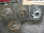
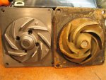
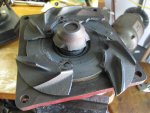
Friday I picked up a new water pump, aluminum radiator (two 1” tubes) and various hoses etc. From Jeff Ismail at ihonlynorth in Loomis. I took a look at the various impellers available as Jeff had the full spectrum. Most interesting to me was with regard to the vane dimension of the three cast impellers. The depth of the oem, factory refurbished and new napa-gmb varies greatly. I’ve included photos to show what we found. The depth of the vane on a new napa is about .040 and when you figure that the vane runs next to the volute that depth determines how much water leaves the pump housing. The oem impeller that Jeff has is easily twice as deep and arguably can move twice the volume of water. The stamped impeller doesn’t have this issue.
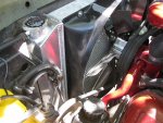
I spent a day and a half installing all the new parts. I mounted the radiator with the shouldered bolts through rubber grommets that Jeff offered and it I expect it will provide some flexibility for the radiator to move somewhat in the framework. The dimensions are all a little different and I ended up with a hayden seven blade flex fan as there wasn’t enough room for my hands to run the fan bolts into the pump for the stock fan with clutch eliminator. I think next time I’ll install the fan to the pump first and then lower the assembly into place and do the bolt up with the four bolts through the water pump flange. Next time. I would add that as all three of my 195 deg thermostats opened to the same degree when boiled on the stove, I installed the shiniest one.
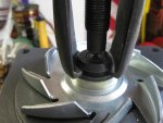
I ground to fit a pulley puller to move the stamped impeller up the shaft and managed to break two pieces of the hub off. I then spent some time with minor bending of the blades, filing and measuring with clay and pieces of solder. My method was to determine which vane had the least clearance and set the others to that height. I clamped the pump flange in a vice and clamped a straight edge to the vice to just touch the tip of the vanes. While not rocket science I am pretty close to .015”. I’m certainly much closer than what came from the parts house.
The test. I took the truck down the freeway for about ten miles with the ac on, on a 90deg day and the engine temp stayed right at 195deg, the thermostat temp. When I would pull off the freeway and idle at a light for a few minutes it would climb to about 203deg but would come back to under 200deg with a few minutes of 25 mph driving. I know more once I’ve had a chance to tow the camping trailer up the mountain and spent some time crawling low range with a tail wind. From what I’ve learned and seen so far I’m pretty comfortable that I have this temperature issue under control.
I spent a day and a half installing all the new parts. I mounted the radiator with the shouldered bolts through rubber grommets that Jeff offered and it I expect it will provide some flexibility for the radiator to move somewhat in the framework. The dimensions are all a little different and I ended up with a hayden seven blade flex fan as there wasn’t enough room for my hands to run the fan bolts into the pump for the stock fan with clutch eliminator. I think next time I’ll install the fan to the pump first and then lower the assembly into place and do the bolt up with the four bolts through the water pump flange. Next time. I would add that as all three of my 195 deg thermostats opened to the same degree when boiled on the stove, I installed the shiniest one.
I ground to fit a pulley puller to move the stamped impeller up the shaft and managed to break two pieces of the hub off. I then spent some time with minor bending of the blades, filing and measuring with clay and pieces of solder. My method was to determine which vane had the least clearance and set the others to that height. I clamped the pump flange in a vice and clamped a straight edge to the vice to just touch the tip of the vanes. While not rocket science I am pretty close to .015”. I’m certainly much closer than what came from the parts house.
The test. I took the truck down the freeway for about ten miles with the ac on, on a 90deg day and the engine temp stayed right at 195deg, the thermostat temp. When I would pull off the freeway and idle at a light for a few minutes it would climb to about 203deg but would come back to under 200deg with a few minutes of 25 mph driving. I know more once I’ve had a chance to tow the camping trailer up the mountain and spent some time crawling low range with a tail wind. From what I’ve learned and seen so far I’m pretty comfortable that I have this temperature issue under control.