Monte Lauer
Active member
Mr. Mayben here are the pictures you requested.


mr. Mayben here are the pictures you requested.
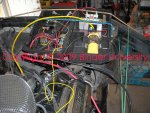
Much better! Now I can see the perspective, I like it, plenty space all around.
Will the fuel cell go between the rad and the tailgate, or on the other side??
Either way...looks like plenty space that won't impact airflow.
mr. Mayben here are the pictures you requested.
Much better! Now I can see the perspective, I like it, plenty space all around.
Will the fuel cell go between the rad and the tailgate, or on the other side??
Either way...looks like plenty space that won't impact airflow.
The fuel cell will go on the other side. I need to start the plumbing and get that 100 amp relay.
mr. Mayben here are the pictures you requested.
Much better! Now I can see the perspective, I like it, plenty space all around.
Will the fuel cell go between the rad and the tailgate, or on the other side??
Either way...looks like plenty space that won't impact airflow.
Ok here is the final product. The engine runs and idles at a cool 150 degrees. Obviously more testing is required, but I think this setup might do the trick.

did ya end up removing the thermostat for now??
How'd the burpin' process work out??
When I come up for the final dial-in, I'll bring a clamp-on ammeter so we can see what the current draw of the entire package actually is when running at full tilt!
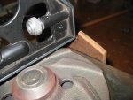
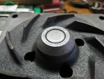
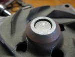
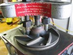
Also...I'd like to install a "pete's plug" at the water outlet so that we can monitor coolant temp at that point with a stinger-type thermocouple. I'll bring the stuff for doing that, but can you post a pic of a npt "port" as close to the coolant outlet as possible so I can prepare the plumbing? Does the actual coolant outlet neck have a tap in it to allow inserting a npt fitting??
The pic shows a "pete's" installed in the coolant outlet on the Ford fe Todd just completed. That aftermarket water neck has a port in it for a coolant temp sensor, it's just to the left of the oil filler in this pic and is a permanent installation now. We now have about four hours run time on the motor, monitoring the temp anytime the engine is running, that pos radiator is just a unit to allow temporary engine run and is nowhere near sufficient for this engine.
We May also wanna put a pete's right at the radiator inlet, it will be interesting to see what the temp differential is between engine outlet and radiator inlet!!!! That can be monitored also with the infrared shooter...but the thermocouple deal is somewhat more indicative of actual heat exchange.
And before folks start nitpicking this lash up, remember...pink is a purpose-built ride for a very specialized task, operating within a very tight budget. Pink's not a trail rig...engine temp is closely monitored and for the time being, the fan(s) will be engaged as needed, based upon how the elimination rounds progress throughout the event and the staging time involved which changes throughout the day. There will be a learning curve involved in order to be able to control engine coolant/engine oil temp/tranny oil temp within it's optimum range for best performance.
There is much more that can be done regarding this setup if needed...but the idea is keep it simple and serviceable between rounds.
Also...I'd like to install a "pete's plug" at the water outlet so that we can monitor coolant temp at that point with a stinger-type thermocouple. I'll bring the stuff for doing that, but can you post a pic of a npt "port" as close to the coolant outlet as possible so I can prepare the plumbing? Does the actual coolant outlet neck have a tap in it to allow inserting a npt fitting??