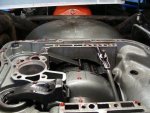
69 Charger - Torqueflite trouble

Chadderbox74

New member
I have a '69 dodge charger with a 383 and 727 torquflite tranny. We've been restoring it for the past several months. Last week, we finally took it for a few short rides (less than a mile each time). Everything worked fine.
Last night, we hooked up the kickdown linkage. Then the tranny started acting up.
In park - it feels like the car is still trying to move forward.
In reverse - same thing, moves forward.
Neutral? Nope. Still tries to move forward.
Drive and low - still moving forward.
So - we unhooked the kickdown linkage... But it didn't fix anything.

I bought the car last fall and the tranny had just been rebuilt.
It's full of atf. Not leaking.

Any ideas?
 
Moving this thread to the correct sub-forum.

The charger has a floor shift mechanism which operates a rod linkage (not cable). Have you verified that the shift linkage (not the kickdown linkage) is correctly connected and adjusted?

Put the vehicle up on four jack stands with all wheels off the ground. Remove the shifter connecting rod from the shift lever on the trans and put the lever in park with your hand and see if that indeed does lock the output shaft (preventing rotation) with the valve body in nuetral.

Then shift the lever by hand to reverse and verify operation...then neutral, then drive. If everything works, then your problem is the shifter installation/adjustment.
 
Michael - thank you! I will try that as soon as I get home this afternoon.
Any idea as to why it worked perfectly for a week - then acted up yesterday?
Why does there seem to be no reverse or neutral? If the shifter was out of adjustment - wouldn't reverse still happen, somewhere along the shifting path?
 
This is actually a very timely thread! Ya sure you ain't a cia agent watchin' every move we make by remote control with a drone?? The fookin' flies in the shop were really buzzin' around yesterday.

Me an scoutboy74 wrapped a 727 rebuild video shoot yesterday regarding a 727 that he'll be installing inna peekup in the future. That video will be posted only on ihon for our member use.

While completing the valve body cleanup/re-assembly, we found that the "rooster comb" had a separation between the shift tower and the actual rooster comb where the two parts are swedged together during manufacture. That one was not so bad that it would have prevented operation, but it would have failed eventually.

It's entirely possible that the same thing has happened inside your trans. That would be the only explanation I have for ya right now until the pan is removed and I can see inside your trans through the use of photographs for documentation. Why has this just happened? Well...shit happens for no apparent reason, otherwise there would not be a need for old fart mechanics like me!

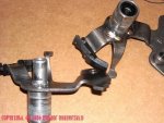
In this pic, the shifter quadrant on the left (what we call the "rooster comb") has loosened where the two parts are swedged together. The one shown on the right has also failed previously and has been repaired by tack-welding using mig with gas.

So what happens is that while the shifter lever on the transmission control tower outside appears to move properly according to the control stick position,...inside,...the rooster comb is not moving/indexing at all. The manual shift valve spool is "stuck" in whatever position the part failed.

That is why I want you to manually move the shift lever on the trans so you can feel (or not feel) the shifter detent positions.

The other thing I've experienced... Is the "tang" of the rooster comb that actually engages the shift valve has broken off. You will find it laying in the pan when ya take it down.

So...the pan is going to have to come off for a much closer inspection/analysis.
 

Attachments

  • Damaged Rooster Comb 003.jpg
    Damaged Rooster Comb 003.jpg
    78.1 KB · Views: 2,530
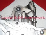
With the pan off the trans and looking up at the valve body rooster comb/shift mechanism, this should be what ya see if the tang is not broken off for the manual shift valve spool.

You can see how the tang engages the cut-out in the end of the manual control valve. That valve is indexed "in" and "out" by the timing of the shifter rooster comb as controlled by the shift lever and shifter mounted in your console on the charger. And it is locked in proper index position by a spring and ball detent unit on the top of the valve body...each detent position corresponds exactly to the shift lever position callout on your shifter console.

That manual shift valve (spool) is indexed in an extremely accurate position that determines each "gear" position, if the spool valve is not exactly lined up inside the valve body, you will have all kinds of control issues including transmission lockup which results in severe internal damage caused by heat buildup as the bands and/or clutches fail.
 

Attachments

  • TF-2 Install 030.jpg
    TF-2 Install 030.jpg
    201.9 KB · Views: 1,839
So - if this is indeed the problem... It can be fixed without removing the tranny?
Can it be welded - or should I get a new rooster comb?
 
If failure of the shift tower/rooster comb is the issue, then only the valve body will have to be removed for repair.

A new service part should be available from any chrysler-product dealer parts department. The aftermarket does not manufacture or supply that part, I just checked again in the catalog I use for reference from the largest wholesale transmission parts supplier in the country.

And most any transmission shop that's been around for years prolly has used parts available. That part was/is used on all variations of the tf 727 except the earliest units that used a "push button" shifter assembly mounted in the dash connected to the valve body with a dedicated cable (last used in the '65/'66 timeframe).

A more common issue is that the plastic follower for the nss switch actually breaks off or the retaining rivet fails. When that happens, the nss system becomes inoperable. The aftermarket does supply a "repair kit" for that plastic follower however so it can be fixed.

If...the rooster comb segment can be indexed back into it's original position on the swedged shift tower, then the part can be repaired by a mig with gas or tig welding process and then dressed with a die grinder so that it articulates correctly and smoothly with no binding. The one I show in my pic has been repaired correctly, I found it in my used parts assortment after scoutboy74 left here Sunday and it was just coincidental that I found it after having encountered this problem on his tranny! We talked about making that repair, but we ended up replacing his rooster comb with another used one I had.
 
Disconnected the shifting linkage, dropped the pan and looked. I ran through the shifting pattern. The rooster comb appears to be moving just fine. So now what?

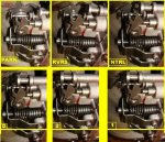
These are pics taken through each of the gears -
 

Attachments

  • Rooster Comb 3.jpg
    Rooster Comb 3.jpg
    87.4 KB · Views: 2,768
Nice pic sequence!

I see nothing that jumps out as an issue. And with the throttle closed, the throttle pressure lever (kickdown lever) has plenty clearance and appears to have popped out all the way due to it's internal spring. That is the correct position when the throttle linkage is closed.

I'm somewhat at a loss here, I've not experienced this condition before!

Before dropping the pan, did you start the motor and shift the trans through the gears by hand with the shift linkage disco'd? If so, did it act the same as described?

Has any type/brand of shift reprogramming/shift improvement kit been installed during the recent rebuild? If so, do you know "which" one was used? How much was the car driven without the kickdown control connected? Is the shifter the oem unit or has it been changed for an aftermarket shifter system? Did the tranny seem to shift ok prior to connecting the kickdown? Under light throttle acceleration, it should have shifted fairly normally (possibly "flaring" on 2>3 shift), but then possibly slipped/"flared" under full throttle acceleration on the 1>2 and 2>3 shift.

I'm just trying to home in on some possible root causes.

Are you comfortable with removing the valve body if needed so that the clutches and servos can be tested using compressed air? It's a nastee job but done with the tranny installed and nothing is going to go flying out other than the large spring between the valve body and the accumulator piston. The piston won't fall out. This thread has some info regarding working with the valve body, and I've one apart right now on the bench for a B&M shift kit install is you need additional pics or info.

If it passes the air pressure test, then I've gotta say there is an issue with some valve positioning in the valve body itself.
 
I did run through the gears (by hand) after disconnecting the shifting linkage. There was no change.

The car shifted absolutely fine before we hooked up the kickdown linkage.

I've never done any work on tranny's - but I will definitely pull the valve body, as it's a learning process - and I don't want to fork out any $ just yet. If I can figure it out by trouble shooting with your help - I'm all for it.

What does pulling the valve body entail? Anything I need to watch-out for?
 
Last edited:
We need to determine if the valve body (and some of the transmission guts) have had any mods such as a "shift improvement kit" installed. Once the valve body is on the bench, I can talk ya through how to determine that I think due to the common "tell-tales" done for those mods.

I'm assuming you are working on your back under the car? If so, when ya look straight up at the valve body, you will need to remove both the shift lever and the throttle pressure lever from the trans. Then remove the three screws that retain the filter and set it aside, more oil will pour out but if ya don't take the filter off, it will be a continuous mess to deal with.

Place the shifter lever/rooster comb in reverse to expose the peg that the parking rod engages into the rooster comb, remove the "e" clip from the peg and push the parking rod up out of the way.

Then carefully remove the n=10 bolts that retain the valve body to the case. If a shift kit has not been installed, there will be a large spring between the valve body pad and the accumulator piston that will fall down. If one of several of the most common shift kits have been installed, then that spring was removed at that time and discarded.

At that point place the valve body on the bench and gimme some various pics so we can determine whatcha got.
 
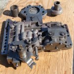
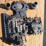
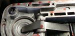
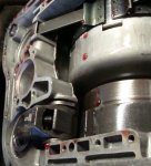
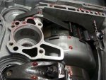
Pulled the valve body off this morning. See anything that raises a red flag?
 

Attachments

  • Valve Body 2.jpg
    Valve Body 2.jpg
    75.2 KB · Views: 4,546
  • Valve Body.jpg
    Valve Body.jpg
    57.3 KB · Views: 1,144
  • Tranny 4.jpg
    Tranny 4.jpg
    29.5 KB · Views: 691
  • Tranny 3.jpg
    Tranny 3.jpg
    61 KB · Views: 781
  • Tranny 2.jpg
    Tranny 2.jpg
    68.8 KB · Views: 727
  • Tranny.jpg
    Tranny.jpg
    69.2 KB · Views: 797
I was just re-reading your posts on this thread, and noticed you said the piston would not fall out.
Well it did.
Both the spring and the piston dropped out when I removed the valve body.
 
If the accumulator piston fell out...that tells me there is no tension on the sealing rings! Are they broken? The piston should have some resistance to being removed when gripped carefully with pliers.

If there was an accumulator spring mounted (it should fall out as nothing retains it other than the valve body), then most likely it does not have a "shift kit" installed. Bu that is not the only clue.

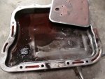
Can you post pics of the metal shavings and the residue in the pan?? Are the shavings aluminum or steel (use a magnet)? I don't want to go into "why" the stuff is present until we get further into the unit.

I've attached a scan of the munroe book page that describes the "air pressure" test for the clutch packs and the bands. Perform that test next and report back! When using the air test at the clutch actuation holes, look into each hole and tell me if either hole has what appears to be a "plug" or a restrictor installed in the hole. The oem setup has no restrictions/plugs at those locations.
 

Attachments

  • 727 Air Check.PDF
    3.7 MB · Views: 837
The shavings are metal - as they are stuck to, and surrounding the magnet in the pan. The seals around the piston are not broke - but the piston slides up and downwithin the cylinder with no resistance.
 
what exactly is going to happen (or should happen) when I apply air to these holes?

As air is applied to each port, you will hear a slight "clunk" from each clutch. When you move to the kickdown (front) servo, the front band will apply (the piston will move to tighten the bands).. Same for the low/reverse band and servo when air is applied.

If both clutches apply and both servos apply, then at least the internal circuitry is correct.
 
tranny pan...:yikes:

That my friend is not a good sign...far worse than "normal sluff" found after say 20k miles!!!

Something is broken.

I'm going to suggest that the overrunning clutch race has broken loose and spun in the case. That is the last component to be accessed/inspected during teardown.

Some folks throw bullshit and say "all 727 trannys are weak in that area". Total crap statement, the overrunning clutch fails because of abuse, too much torque/hp for the particular tranny build, or it was damaged previously and either overlooked or ignored during the previous rebuild (most likely).

Some of that metallic residue is steel (the inner and outer races, springs and rollers), and some of it is the aluminum case itself which is possibly now badly stripped and will not hold an oem press-in race. That is when we install a "bolt-in sprag" which is a repair component used in order to hopefully salvage the case, if not the case is destroyed.
 
Back
Top