Clutch Question

harrywt

Member
This is part of my rebuild but I created a new thread because I wanted to get more attention on this particular issue.

I borrowed this picture from the parts listing here at IHPA, I bought my clutch here. I thought I took a picture of my clutch after dropping the tranny but must be in my virtual memory.

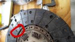
Anyway, we are focusing on the three screws on the end of the actuator arms of the clutch. Red arrow in this picture
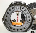
Clutch_generic.jpg

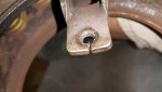
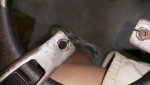
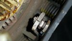
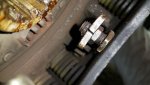
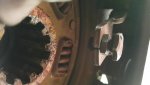
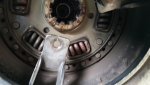
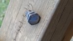
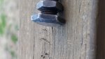
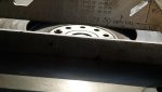
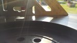
I noticed that all three screws are worn down and galled on top. The clutch has only been in service for a year. I believe that the throwout bearing always had contact with the screws even with foot off of the clutch pedal.
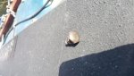
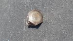
2016-04-17 15.49.49.jpg

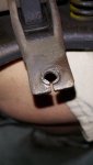
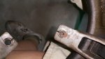
2016-04-17 15.49.57.jpg

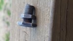
One of the screws spun and stripped its threads
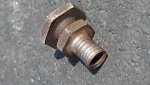
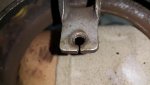
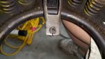
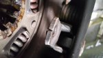
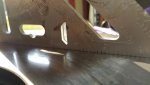
2016-04-17 15.50.11.jpg

The hole in the clutch arm is stripped also but the screw was still in place so the whole is not too cammed out.

My guess is that I could put a similar screw in there with a backing nut and it would be held in the proper place.

First of all I need a sanity check, is this a stupid thing to do?

If it is, can I simply replace the actuator arm of the clutch? Since the clutch is only a year old I think replacement is too severe a solution. Especially since the shipping charge to korea might be a bit high....

Please share your wisdom!
 
That's sure a bummer to find when you're out of town and in some foreign land. Looks to me like the pp rebuilder bodged it by brazing the nut on the adjuster bolt.

It looks to me like you've got 2 choices, get a new pressure plate or try having someone there braze the bolt back on. Due to the difficulties of repairing a unsuccessful repair, I'd go with a new pp. Those 3 bolts need to be adjusted to the correct height or you'll have some nasty chatter in during clutch engagement.

Not that it's a real big deal at the speed IH engines spin, but changing the amount of weight on 1 arm May cause vibrations at higher rpm's.

Another option, if the $$$ to get a new pp is outrageous, is to adapt something locally sourced for a truck application.
 
If you can follow the clutch setup as outlined in the rebuild section of the manual, I'd say go for what you can fix. Those boltheads have a specific distance they're set at. If they were in contact with the throwout assembly full time, then the clutch pedal linkage and pedal height also needs looking at.

On another note, what do your "neighbors" think of your Scout :) ?
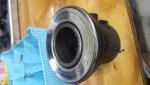
 
Can you tell if the stripped end of the bolt is 3/8?
Like greg said the 3 actuation fingers need to be at some common distance relative to the plane of the to bearing.
While we are on the to bearing I recommend checking it and regreasing it if it is still serviceable.

I see that you don't likely have a big supply of inch sized hardware near you so sub what ever size of metric bolt for the below ones. 10mm = .393 11=.433

here is what I would investigate. If the stripped hole is a 3/8 bolt thread, you can run a 7/16-20 tap through the bad finger and replace the bolt with the 7/16-20 size and jam nut. You could
also grind the new bolt head to a rounded shape not unlike the original one.
Once you have the new bolt in place adjust it to match the other two using some location on the disk as a datum. Lock the jam nut.

One other option is to set the old bolt in the finger at the correct height and weld it in place. Two good tack welds will do fine. Might consider the same attachment for the other two.
 
Last edited:
The constant contact is sort of my fault. Funky noise had been there when I bought truck. I rebuilt the motor, got new clutch kit and throwout bearing and had flywheel surfaced. Put it all back together and noise still there.

One week later and I am in korea. Wife dutifully takes Scout to have tailpipes installed and "expert" tells her he fixed noise by adjusting clutch.

Scout gets here to korea and I conveniently ignored problem. I knew tranny going bad. In fact a real expert diagnosed noise just before putting Scout on ship, input shaft bearings. (actually turned out to be countershaft bearing, see other thread soon)

when tranny gave up ghost maybe also made clutch worse, at least the actuator arms didn't get bent

the nice thing is tha there are literally hundreds of hardware stores, machine shops and bolt stores here. I have been building relationships for the past two years. They all love my Scout.

More soon

if you can follow the clutch setup as outlined in the rebuild section of the manual, I'd say go for what you can fix. Those boltheads have a specific distance they're set at. If they were in contact with the throwout assembly full time, then the clutch pedal linkage and pedal height also needs looking at.

On another note, what do your "neighbors" think of your Scout :) ?
 
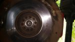
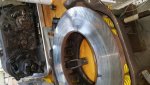
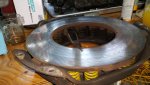
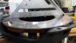
I took a bunch more pictures today. I removed the clutch to have a better look at it.

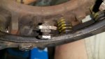
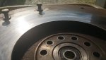
I notice that the remaining two spacer bolts are set at different depths into their respective actuator arms. I suppose it is not surprising that the ends of the arms are not co-planar but I was surprised at how easy it is to see the difference between the two bolts.

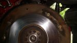
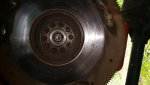
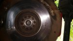
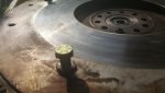
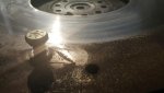
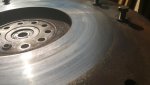
In regard to the bolts constantly riding against the throw out bearing I looked for signs of the friction plate sliding. The flywheel looks ok in person, you can easily see the swirl marks from the flycutter when I had it surfaced.

In the pictures it does look like the friction plate was sliding. When I was driving it it always felt like I had a good lock up between engine and tranny.

The clutch assembly including the throw out bearing, has maybe 5000 miles on it.

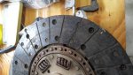
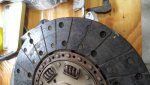
When you look at the friction plate the rivet heads seem awfully close to the surface. I cant remember what it looked like when I installed it.

Back to the spacer bolts. The arm with the stripped bolt is not as damaged as I thought. I was even able to thread one of good bolts into it and it snugged up.

It looks like they used a tapered punch to make the holes to be tapped. The bent back material adds a little more depth to be threaded. I am thinking about grinding the back faces smooth and putting three new bolts with nuts on both sides of the arm.

I like the tack weld idea but they don't have mig welders here, not even flux core wire, only arc welders with large sticks. I suppose I could find somebody with a precise welder. There are so many shops here, it is really heaven for anybody who likes to tinker as much as I do

the roof rack on my little damas is "home made". I laid it all out in my cad program and had it made at a machine shop for only a little more money than a good quality mass produced one at home.

Please give me any and all opinions that you might have.

2016-04-23 15.12.17.jpg

2016-04-23 15.07.27.jpg

2016-04-23 15.07.07.jpg

2016-04-23 15.06.51.jpg

2016-04-23 15.06.31.jpg

2016-04-23 15.06.25.jpg

2016-04-23 15.06.19.jpg

2016-04-23 14.27.52.jpg

2016-04-23 14.27.19.jpg

2016-04-23 14.27.39.jpg

2016-04-23 15.12.17.jpg

2016-04-23 15.07.27.jpg

2016-04-23 15.07.07.jpg

2016-04-23 15.06.51.jpg

2016-04-23 15.06.31.jpg

2016-04-23 15.06.25.jpg

2016-04-23 15.06.19.jpg

2016-04-23 14.27.52.jpg

2016-04-23 14.27.19.jpg

2016-04-23 14.27.39.jpg

2016-04-23 11.32.46.jpg

2016-04-23 11.32.42.jpg

2016-04-23 11.32.39.jpg

2016-04-23 11.17.56.jpg

2016-04-23 11.16.47.jpg

2016-04-23 11.15.34.jpg

2016-04-23 11.15.27.jpg

2016-04-23 11.15.18.jpg
 
Your pressure plate is different than the one I have with my 258. Mine doesn't have those adjustment screws, just different arms. That said, it looks to me like someone had trouble getting those screws out of yours at some point, and took a dremel with a cutoff wheel and slit the ends of the arms to help get the screws out. Probably enough pressure gets put on them to let those slits open up and allow the screws to move around. If you add a nuts to the other side, I would consider having them tig welded onto the back.
 
As I have mentioned, this was brand new from IHPA when I installed it. And yes, tig is prob the way to go, thanks.

your pressure plate is different than the one I have with my 258. Mine doesn't have those adjustment screws, just different arms. That said, it looks to me like someone had trouble getting those screws out of yours at some point, and took a dremel with a cutoff wheel and slit the ends of the arms to help get the screws out. Probably enough pressure gets put on them to let those slits open up and allow the screws to move around. If you add a nuts to the other side, I would consider having them tig welded onto the back.
 
What the heck is that gouge on the face of the flywheel. You've got to have a smooth, flat surface all the way around. That flywheel needs to be properly resurfaced. It looks like that gouge has worn the clutch disk badly as it looks like one of the rivets is worn. My suggestion is to find a local clutch rebuilder to redo your pp and disk.

The slots in the ends of the arms are normal.
 
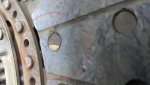
Do you mean the pattern at the arrow in this picture? I believe that that is a little rust. I will take more pictures but there are no gouges in the flywheel. The photos make the flywheel look worse than it is. It actually looks quite nice. Anyway, wouldn't a rivet from the friction plate make a circular gouge rather than one along a radius?

2016-04-23 11.32.39_A.jpg

what the heck is that gouge on the face of the flywheel. You've got to have a smooth, flat surface all the way around. That flywheel needs to be properly resurfaced. It looks like that gouge has worn the clutch disk badly as it looks like one of the rivets is worn. My suggestion is to find a local clutch rebuilder to redo your pp and disk.

The slots in the ends of the arms are normal.
 
If you had access to a replacement or having it relined I would recommend that but in your situation it is safe to reuse it.
It is really fine. It does show some wear but nothing that will effect it's performance
 
Wow, good eyes. I'll check this evening, I think that I will bring a pair of calipers home as well. Hard to understand having a friction plate with so few miles on it being worn out. Guess combination of tranny going bad and bad linkage adjustment.

is the circled spot a rivet with wear on it's head?
 
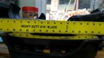
So the rivet in question looks like it is improperly installed. I measured the total thickness of the friction plate and it is 0.301" +/- 0.001" which is nominal as one would exxpect a new plate to be 0.300-0.325" but I don't know what this one was.

I asked Chad to give me a price for a new one with to and spindle bearings

2016-04-25 18.21.00.jpg

2016-04-25 18.21.58.jpg

2016-04-25 18.21.53.jpg

2016-04-25 18.20.53.jpg
 
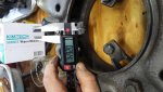
So I am quite certain that this is a 5/16-24. I am pissed off at my self for not looking for the direction of the galling relative to the throw out bearing. Maybe the last screw will tell me and/or the to bearing

2016-04-25 18.16.49.jpg

2016-04-25 18.39.12.jpg

2016-04-25 18.39.27.jpg

2016-04-25 18.39.31.jpg
 
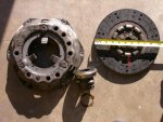
So my service manual doesn't cover the clutch I have. It was sold to me by IHPA as an 11" borg & beck. I got a catalog from mid-america clutch and they show my clutch as a rockford. See page one of the attached pdf.

What I need are dimensions a & b that you see on page two. Page three is a list of specs for various clutches. Maybe someone can find the clutch I have in another service manual and send me the specs?

View attachment Clutch Adjustments.pdf
 
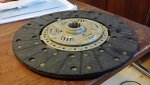
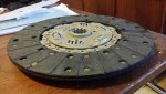
So I found these pics in my engine rebuild thread. Time for new friction plate. Got to figure out why it wore so much

friction_plate_new_01.jpg

friction_plate_new_02.jpg
 
Like the pdf, very informative. Apparently you can mix and match. Mine has the top bork and beck three finger pressure plate with a rockford clutch disc. Had the disc and pressure plate that came out rebuilt at ba friction materials in san jose CA. They turned them around in a day, even replaced the fingers. Has about 10k miles on it now. Wondering if the clutch and pressure plate you put in matched what you took out? When I took mine out, the clutch disc was installed backwards, and those raised bumps on the disc were half way through the flywheel bolts, wouldn't that have been fun.
 

Attachments

  • 258 clutch.jpg
    258 clutch.jpg
    83.9 KB · Views: 449
My 1970 mach I had a cleveland...

Getting the names of the parts right saves time. It's not so bad now with the internet so you can compare pictures to your existing parts. Back in the day you had to wait until it arrived in the mail

like the pdf, very informative. Apparently you can mix and match. Mine has the top bork and beck three finger pressure plate with a rockford clutch disc. Had the disc and pressure plate that came out rebuilt at ba friction materials in san jose CA. They turned them around in a day, even replaced the fingers. Has about 10k miles on it now. Wondering if the clutch and pressure plate you put in matched what you took out? When I took mine out, the clutch disc was installed backwards, and those raised bumps on the disc were half way through the flywheel bolts, wouldn't that have been fun.
 
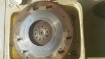
Flywheel out.

2016-04-30 16.33.14.jpg

2016-04-30 16.33.22.jpg

2016-04-30 16.33.26.jpg

2016-04-30 16.33.29.jpg

2016-04-30 16.33.32.jpg

______________________________________________
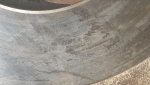
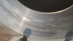
some crazing seen here (below), higher heat? It's hard to see. I cleaned the flywheel and took more photos. Shown in next post

2016-04-30 16.33.44.jpg

2016-04-30 16.34.03.jpg

2016-04-30 16.34.08.jpg
 
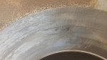
Cleaned flywheel with kerosene and steel wool.

2016-04-30 16.34.11.jpg

_________________________________________
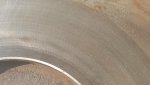
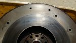
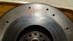
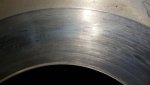
next two are same picture, added arrows tothe second one. This is the crazing I spoke of earlier. There is a slight ridge where the perimeter of the friction plate met the flywheel. It is barely to be felt with a fingernail and not seen with the straightedge. I estimate it to be no more than 2-3 thousandths of an inch.

2016-04-30 16.43.37.jpg

2016-04-30 16.43.37A.jpg

2016-04-30 16.43.41.jpg

2016-04-30 16.44.16.jpg

2016-04-30 16.44.43.jpg

2016-04-30 16.45.59.jpg

2016-04-30 16.46.08.jpg
 
That looks a lot better than I thought it did in the first set of photos. Just have it resurfaced and you'll be good to go.
 
Back
Top