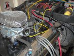
I believe that I now have the vacuum lines setup correctly. I looked at a few more engine setups and found that Robert was correct in that the pcv valve should be in the valley pan cover. I picked one up from the parts store and it fit perfectly. .
The pcv valve should be routed to the intake manifold -- where your "multi" connections are...
I pulled and plugged the line from the speed sensor. This seems to have absolutly no affect on how the engine performs.
Probably would not notice anything -- I think it affects ("changes") the vacuum advance during some combination of road speed and engine operating temp -- when all "pieces" are
in place (tvs switches, egr valve, etc).
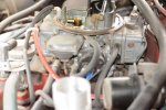
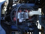
now I have one last thing...now that I removed the pcv valve from the valve cover, do I need to get a flame arresstor or can I just plug the hole? Does it matter? Btw in the photo it is on the passenger side as during the rebuild I swapped the valve covers to make it easier to access the oil fill cap.
Yes, you need a flame arrestor - so that the engine itself "breathes" internally and does not build up pressure.
I thought michael would reply, but maybe his internet / phone situation is still a mess.
Imo, you have valve covers from an "earlier version" / earlier year engine (pcv plumbing wise) -- why I asked about the year of the engine.
There should be a driver's side valve cover without an oil fill cap with the same pipe fitting that your current pass side valve cover has.
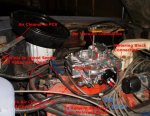
The flame arrestor goes in the driver's side valve cover and a hose runs to the base of the air cleaner (where you had your pcv valve connected). You need to "construct" a connection (that does not kink the hose) as the stock "hard-formed" 90+ degree bend rubber hose is not available.
There also should be a pass side valve cover (version) with just the oil fill cap and no pipe fitting.
I guess you could put a flame aresstor in your pass side valve cover and run the hose that you had on the pcv valve to the air cleaner.


 the flame arrestor is an IH part. Looks like they are on back order (light line).