

You are using an out of date browser. It may not display this or other websites correctly.
You should upgrade or use an alternative browser.
You should upgrade or use an alternative browser.
The Ultimate IH Fourbanger
- Thread starter Michael Mayben
- Start date

Robert Kenney
Super Moderator
Not much movement on this project. Took on helping a friend restoring a 71 c10 short bed. Rust repair right now and flipping the rear axle to lower it 5+ like the front. Nothing like a hammered c10.
Man I understand too well. I have an '80 fsj getting a full power-plant swap that I have to have done by the end of May as my daughters graduation present (you gotta love a girl that wants a wagoneer instead of something new) and a tj that I am rebuilding too, so I bought a Scout 'cause I don't have enough projects going...
Robert Kenney
Super Moderator
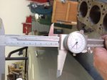
The land cruiser block is at the machine shop so I had some time to make progress on the 188 inch 152 stroker. Mounted the nos block on a spare engine stand and began mapping the cylinder wall thickness. First I marked a 12 gauge solid wire at 1/16 increments to get a good idea. Accessing the water side wall I measured through the cooling passage holes and marked the deck 1-3. 1 means 1/16 3 = 3/16 from the hole edge to the water side of the bore. Then I measured the hole to the piston side of the bore subtracting the gauged 1-3 reading and marked the deck in a decimal witch represents the bore thickness. The thinnest I got that way was .318. That's good because after boring to 4" I still have .25+ wall thickness. I like 3/16 (.1875) + for good stability. Next I'll need a set of main bearings to mock the crank and a cut down piston to mock the crank and rods. It should go quickly from here on out.
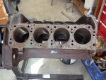
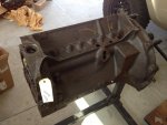
Also good the block being a nos IH service part, it had new IH cam bearings in it. They should be ok as they have never seen service or any abuse. I will leave them be.
Also good the block being a nos IH service part, it had new IH cam bearings in it. They should be ok as they have never seen service or any abuse. I will leave them be.
Robert Kenney
Super Moderator
Sourced a new 396 bbc piston and machined it to fit the stock bore. This is only for mock and clearance checks so it is not functional any more. Machined the diameter and compression distance to the numbers I calculated.
Installed the cam. Spins with only fingers on the nose. IH did a great job installing the bearings. The rear cam bearing is installed as we expected, about 3/32 below the rear most surface that the plate seats on. The lifter bores and lobes are correct with the lobe favoring the rear of the lifter bore. The lobe is supposed to have the taper proud to the rear of the lobe.
There is a lot of room between the rod and cam. The 4 bangers also don't have a lobe that is inline with the rod but even a v8 will have no problems.
The same clearance is true with the rod to block and piston to crank counter weights.
Here are a few pictures for reference.
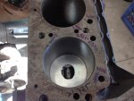
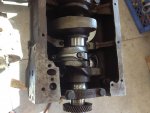
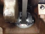
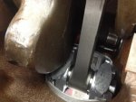
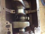
Installed the cam. Spins with only fingers on the nose. IH did a great job installing the bearings. The rear cam bearing is installed as we expected, about 3/32 below the rear most surface that the plate seats on. The lifter bores and lobes are correct with the lobe favoring the rear of the lifter bore. The lobe is supposed to have the taper proud to the rear of the lobe.
There is a lot of room between the rod and cam. The 4 bangers also don't have a lobe that is inline with the rod but even a v8 will have no problems.
The same clearance is true with the rod to block and piston to crank counter weights.
Here are a few pictures for reference.
Mark Pietz
Member
Wow, getting a bit closer….
Robert Kenney
Super Moderator
I'm going to resurrect this project. The new Scout didn't materialize for a number of reasons, so now I can justify rolling my backup 152 into my shop and begin mocking up the intake manifold, exhaust/turbo manifold and intake plenum.
The first generation of this project will be a stock stroke 152 that may have a non stock bore, rod length and some comprehensive port massaging. .
It will have the two DHLA40H side draught DeLortos, and a properly sized turbo which I already own. They will be running in the typical blow through configuration and most likely incorporate an after cooler.
Stay tuned if you are interested. Don't hesitate to kick me if I slack off on making progress.

The first generation of this project will be a stock stroke 152 that may have a non stock bore, rod length and some comprehensive port massaging. .
It will have the two DHLA40H side draught DeLortos, and a properly sized turbo which I already own. They will be running in the typical blow through configuration and most likely incorporate an after cooler.
Stay tuned if you are interested. Don't hesitate to kick me if I slack off on making progress.
Last edited:
Mark Pietz
Member
Continuing to watch with interest!
Robert Kenney
Super Moderator
So far I got the extra engine stripped of parts that will be replaced by new the intake and exhaust assemblies. Mounted both intake and exhaust flanges. I'm getting ready to form the round to square, trap, and rectangle transitions for the ports this weekend. Purchased a couple of 2 foot lengths of 304 SS tubing 1-5/8 round in 18 and 16 gauge + 1-1/4 18 gauge from Burns Stainless.
Also bought one of IHPA's mini high torque gear reduction starters to free up as much room as possible for the exhaust and turbo. The OEM direct drive starter is big and makes things tight.
Also bought one of IHPA's mini high torque gear reduction starters to free up as much room as possible for the exhaust and turbo. The OEM direct drive starter is big and makes things tight.
Robert Kenney
Super Moderator
Went out to the shop early this morning with my cup of coffee, and tested my home made forming tools. They made easy work of the transition stubs. Need to complete the set and a few extra cause I know I'll screw a couple up fabricating the manifolds.
Cut 2-1/4 inch pieces of the correct tubing on the band saw, used the lathe to make the ends square and flat, and used my mill vice to press form the shapes. Also helped the forming process with a round face body hammer.
I think the 1-1/4 OD tube that I chose for the coolant ports is small. I will order a piece of 1-3/8 and try again next weekend.
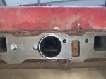
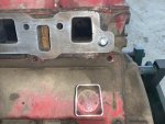
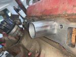
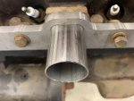
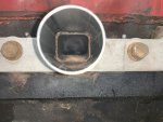
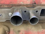
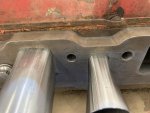
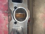
Cut 2-1/4 inch pieces of the correct tubing on the band saw, used the lathe to make the ends square and flat, and used my mill vice to press form the shapes. Also helped the forming process with a round face body hammer.
I think the 1-1/4 OD tube that I chose for the coolant ports is small. I will order a piece of 1-3/8 and try again next weekend.
Last edited:
Robert Kenney
Super Moderator
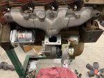
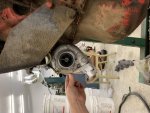
I think I am going to try and utilize the OEM 3 bolt exhaust manifold. Did a very rough mock up, and I think it will work. Plenty of space for the turbo charger and plumbing.
The compressor housing will index about 80-85 degrees to face the outlet more of less up if I need to. I plan on having a charge air cooler so down facing is better as it would go below the engine mount bracket and through the existing oblong 3X4.5 hole in the core support, through the cooler and back through the same hole.
I went ahead and bought the exhaust and intake flanges so I could see how they would.
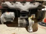
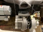
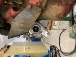
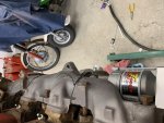
The compressor housing will index about 80-85 degrees to face the outlet more of less up if I need to. I plan on having a charge air cooler so down facing is better as it would go below the engine mount bracket and through the existing oblong 3X4.5 hole in the core support, through the cooler and back through the same hole.
I went ahead and bought the exhaust and intake flanges so I could see how they would.
Mark Pietz
Member
Been a long time since I had a model 80. So there will be room above the frame rail? Just trying to visualize it.
Last edited:
Robert Kenney
Super Moderator
It tucks in under the exhaust manifold. Plenty of room.
Mark Pietz
Member
Looks like a 152T 3-bolt manifold.
Robert Kenney
Super Moderator
You might be on to something. I have two of these manifolds and one for sure came from a 152T. This mock up engine has a special port in the lifter cover that was likely the oil return for the oem turbo?.
I had just assumed that these were standard three bolt exhaust manifolds. I had better use one that I can source new.
I had just assumed that these were standard three bolt exhaust manifolds. I had better use one that I can source new.
Robert Kenney
Super Moderator
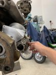
Got my 2 bold manifold and swapped it on to the mock up engine. It is exactly the same flange height as the 3 bolt 152T manifold. It will have the rear bolt in a difficult location so I'll use a stud threaded into the flange and a nut up above if it is a problem. Pix of course.
Robert Kenney
Super Moderator
Does anybody know if a oem turbocharged 152 was stamped with a “T” in its ID pad, EG 152T instead of 152E or 152A?
Mark Pietz
Member
Does anybody know if a oem turbocharged 152 was stamped with a “T” in its ID pad, EG 152T instead of 152E or 152A?
For some reason I have one left-over, fubar 152T compressor housing and it still has that little ID plate on it. Is what you are looking for on that plate or perhaps cast onto the housing's surface?
How does the overall diameter of that T25 compressor (or exhaust) housing(s) compare to the original TRW turbo? Smaller, I imagine?
Robert Kenney
Super Moderator
I was referring to the engine block pad where they also stamp the SN of the engine. I think the mock-up was once a 152T from the parts on it. The block is stamped 152E.
This GT turbo is smaller but will flow enough for 270 hp but has smaller in and out diameters than the OEM unit.
This GT turbo is smaller but will flow enough for 270 hp but has smaller in and out diameters than the OEM unit.
Mark Pietz
Member
I was referring to the engine block pad where they also stamp the SN of the engine. I think the mock-up was once a 152T from the parts on it. The block is stamped 152E.
This GT turbo is smaller but will flow enough for 270 hp but has smaller in and out diameters than the OEM unit.
Sorry I misinterpreted your question. It's a good one - like to know the answer to that myself. I'd post this on the BB. There are a couple of people that still having running 152Ts.
Robert Kenney
Super Moderator
Still mulling over the location for the turbo. I have sourced another GT turbo with journal bearings and no water required. It has better turbine flow capacity and still will support 250 hp. It is the gt2252.
Still however mounting it low like I have photographed has some drawbacks:
1) Being low exposes the turbo to water and other objects.
2) Tucking it in close to the block for space, will create some plumbing issues. The OEM manifold to turbo inlet is a tough angle. While doable, I will end up with having to preassemble the turbo and manifold prior to installing on to the engine. As well as requiring that the oil drain be plumbed into the pan with little drop.
I'll break out my 152 T exhaust manifold spacer (sorry Mark) and mount the manifold pointing up for mocking purposes. I wonder how bad repoping the spacer would be? probably SS or steel billet. Or find an extra one. If there are any members willing to part with one PM me.
I'll tinker with the options and see what makes the most sense.
Still however mounting it low like I have photographed has some drawbacks:
1) Being low exposes the turbo to water and other objects.
2) Tucking it in close to the block for space, will create some plumbing issues. The OEM manifold to turbo inlet is a tough angle. While doable, I will end up with having to preassemble the turbo and manifold prior to installing on to the engine. As well as requiring that the oil drain be plumbed into the pan with little drop.
I'll break out my 152 T exhaust manifold spacer (sorry Mark) and mount the manifold pointing up for mocking purposes. I wonder how bad repoping the spacer would be? probably SS or steel billet
. Or find an extra one. If there are any members willing to part with one PM me.I'll tinker with the options and see what makes the most sense.
Robert Kenney
Super Moderator
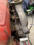
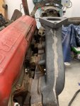
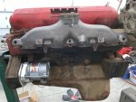
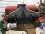
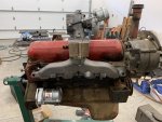
Bolted the 152T exhaust manifold wedge/spacer and the new 2 bolt manifold. The spacer is in super nice condition. All threads and surfaces are perfect. It makes a nice combination with the smaller modern turbocharger. Will need to make the rectangle to round adapter riser but that shouldn't be bad. The little turbo sitting up on the manifold looks odd.
Last edited:
Mark Pietz
Member
Lookin' nice! So...do you think it is possible to get the dimensions from that spacer so one could be duplicated? Costly, maybe, but hmmm...
Edit: Robert, this engine is going back into a model 80, with that 15 degree rotation, right? Are you going to upgrade the T90?
Edit: Robert, this engine is going back into a model 80, with that 15 degree rotation, right? Are you going to upgrade the T90?
Last edited:
Robert Kenney
Super Moderator
I think a custom "Log Styled" manifold would be better and cheaper. I would want it to be SS rather than any steel.
Yes to the stock Scout 80. The T90 should survive non abusive driving.
My single biggest concern of this whole project is the 4 bolt/cylinder head configuration on these SV's. My concern may be unfounded as other manufactures successfully utilize this configuration, but from a forced induction perspective, I have the most experience with GM's and they use 5/cyl.
It won't take long to find out where the weak link is.
Yes to the stock Scout 80. The T90 should survive non abusive driving.
My single biggest concern of this whole project is the 4 bolt/cylinder head configuration on these SV's. My concern may be unfounded as other manufactures successfully utilize this configuration, but from a forced induction perspective, I have the most experience with GM's and they use 5/cyl.
It won't take long to find out where the weak link is.
Last edited:
Mark Pietz
Member
How much boost you wanting to run? I'm going to keep my next iteration at 7#, which is probably well within the safety margin. About your T-90. Maybe you can score one of those special 152T T-90s listed in the Sales brochure, you know, the ones with "the shot peened gears for added strength"  .
.
I can tell from your pics that the plane of your exhaust outlet is horizontal; that's due to the 15 degree rotation of the engine itself. When I had those parts on my 196, the plane was rotated 15 degrees outward due to the normal placement of the block. I recall early on you advising me to use a modern turbo, and so now I come around to your way of thinking. I knew that to do that an adaptor of some sort would have to be made to replace the iron elbow, and it would couple the turbo closer to the engine. Looks like you are blazing the trail on fabbing that adaptor. What makes this so appealing to me now is that I think the T25 is a smaller package than the old TRW, and would eliminate the hood clearance problem I had, something like 1/2" or so.
. I can tell from your pics that the plane of your exhaust outlet is horizontal; that's due to the 15 degree rotation of the engine itself. When I had those parts on my 196, the plane was rotated 15 degrees outward due to the normal placement of the block. I recall early on you advising me to use a modern turbo, and so now I come around to your way of thinking. I knew that to do that an adaptor of some sort would have to be made to replace the iron elbow, and it would couple the turbo closer to the engine. Looks like you are blazing the trail on fabbing that adaptor. What makes this so appealing to me now is that I think the T25 is a smaller package than the old TRW, and would eliminate the hood clearance problem I had, something like 1/2" or so.