The Ultimate IH Fourbanger

So ...where do I find the budget 152 build up thread? I'm thinking: cam, header, port & polish, and fuel injection. Do 304 cams work in 152s and is there a 2.5l f.I. Option you have been considering? Yeah funny noob questions. :icon_eh: thanks guys! I love this forum!
 
Mike,

real sorry we missed your question.... Here it goes, better late than never:winky:

so ...where do I find the budget 152 build up thread? I'm thinking: cam, header, port & polish, and fuel injection.

We don't have a budget 2.5l build here yet but I'm sure we could work you up a nice spec for relatively little money.

What do ya want to get out of it? More torque will take a bit of effort but a good cam with high lift and short duration say 202-204 intake duration, compression say 9-1 for 87 regular or 9.5-1 and use mid grade 89 octane. We can have basically any profile ground on a 4 popper cam core. The 4 cylinder cam core is no longer made but we have a rebuilder who builds up the old lobes so the proper lift integral can be attained. A simple regrind looses some lobe volume and will never put out the same torque curve as a fully rebuilt lobe.

A header won't do much for torque I would stay with the oe cast iron one but redo from the collector back in 2 1/4 and a good flowing muffler

a suitable TBI system can be transplanted from a 2.5l j$$p. Or smiler sized GM product. Then you get to tune it. :gringrin: I vote stay with a carb. Maybe dhla's od dcoe's. 28-32 mm chokes. Way more torque and hp. Efi is for emissions imo

port and polish with care if you want torque, to much port volume can hurt more than it helps. Properly done there are gains to be made here.

Do 304 cams work in 152s and is there a 2.5l f.I. Option you have been considering? Yeah funny noob questions. :icon_eh: thanks guys! I love this forum!

The 304 cam won't work. Firing order, kills the idea but the lobes are in the correct location with exception of the fuel pump lobe which doesn't exist on the v8 cam per say.

We would be happy to start a 2.5l build thread if you wanted to have a go at it. I have a some what stock 2.5 in my 65 and it does very well.
 
Last edited:
Hmmm...well there seem to be dead ends on alot of the easy roads I try to take with this Scout. I want to run my Scout offroad only. I'm trying to stay away from the v8 swap and just build what I have. I know fuel injection will work better in the off kilter situations I'm planning on getting myself into. It sounds like the old muscle car engine buildup ideas dont work for the 152. Can I ever expect over 100 hp? Maybe 150 lbs./ft. Of torque? Enough to push 35's around strongly? Maybe I'm looking at it all:shocked: the wrong way, but there seriously isnt a way to get a new cam either? Wow, this is gonna be rough. Thanks -Mike
 
hmmm...well there seem to be dead ends on alot of the easy roads I try to take with this Scout. I want to run my Scout offroad only. I'm trying to stay away from the v8 swap and just build what I have. I know fuel injection will work better in the off kilter situations I'm planning on getting myself into. It sounds like the old muscle car engine buildup ideas dont work for the 152. Can I ever expect over 100 hp? Maybe 150 lbs./ft. Of torque? Enough to push 35's around strongly? Maybe I'm looking at it all:shocked: the wrong way, but there seriously isnt a way to get a new cam either? Wow, this is gonna be rough. Thanks -Mike

There's a guy in our club with a stock 152 running 37's. It's all about gearing. It's an offroad only truck and hangs just fine with big v-8's and anything else on the trail.
 
hmmm...well there seem to be dead ends on alot of the easy roads I try to take with this Scout. I want to run my Scout offroad only. I'm trying to stay away from the v8 swap and just build what I have. I know fuel injection will work better in the off kilter situations I'm planning on getting myself into. It sounds like the old muscle car engine buildup ideas dont work for the 152. Can I ever expect over 100 hp? Maybe 150 lbs./ft. Of torque? Enough to push 35's around strongly? Maybe I'm looking at it all:shocked: the wrong way, but there seriously isnt a way to get a new cam either? Wow, this is gonna be rough. Thanks -Mike

No dead ends at all really!!! Sorry if I sounded that way.:icon_eek: 100 hp easy 150 ft./lb May take stroking the 152 crank and boring .060 over to 160 inches

your 152 can be modified to make in excess of 230 hp with stroke mods to 188 inches but it all comes to money. Pistons rods and a stroked 196 crank.

Stroking a 152 to 188-190 inches will be a better performer that a 196 on a trail or the street. It will make more peak torque, make more torque earlier and make more hp more efficiently. Also run on regular.

Add gearing changes that carl mentioned and you will have one hell of a rig with a 4 banger to boot.

So it comes down to pick your poison.
 
We have verified that an sv cam can be used as a core for a weld-up/regrind by our cam supplier. The "unused" lobes will be removed.

The biggest hurdle is the fuel pump cam, that is not present onna sv cam blank or core, there is a lifter lobe present in it's place.

So we can have the lifter lobe onna sv core turned into a fuel pump lobe by adding some weld material to one end. Then a fuel pump lobe will have to be ground into the welded lobe. This is normal, everyday stuff for a cam shop.

So we have a few I-4 cam cores in the camdude's "bank" now, both are I-4...so we can supply nearly any grind requested for an I-4 right now onna original IH I-4 cam core with weldup.

The cams for sv motors are ground on new blanks, unless for some reason a customer wants a weld-up/regrind on their existing core. So we have several avenues for cams around here, regrinds (with nearly any profile imaginable), new stock cams, several "brand name" cams, etc.
 
Last edited:
Subscribed!

Since my 152 got bogged down in the snow this year I'm looking for more power. A hot 152 or 196 would be preferred over the downtime associated with a 258 or 4bt.
 
I'm still gathering components for the stroker motor, the lack of cubic dinero definitely slows down this process.

But since I'm in shop cleanup/purge mode I'm prepping the peripheral components for the build as I scavenge though my pile of donor schnizz.

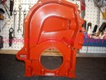
Here's a shot of the prepped timing cover interior. This cover has had the oil filler removed and the hole blocked with the appropriate core plug...which happens to be the same size plug as used to fill the penetrations in the oem-design aluminum intake manifold.

Then the interior of the cover (and all internal engine component surfaces except fasteners) was shot with what is generically referred to as "glyptal":

home page

I'm using a version of the stuff manufactured by aervoe industries labeled as "insulating epoxy coating", p/n 401:

welcome!

Many years ago, in engine building, we used rustoleum "red" primer and applied with a brush, a very time consuming and nasty job. Idea is to seal the interior of the sterilized engine with a product that is very "slick" and will shed oil readily, while sealing the porosity of any castings and embedding any microscopic particle that might rise to the surface of the metallic components during operation. In the old days, "glyptal" was a much more advanced product to use, but also was much more difficult to deal with in it's old formulations.

This type product is typically used today in commercial electric motor shops to insulate freshly re-manufactured armatures, coils, etc. Two cans of this stuff will do an entire engine internally, including the head(s). It must be masked off any bearing saddles and kept out of machined/threaded penetrations as it builds a thick film and can be difficult to remove once it cures. It's also really not something ya wanna breathe so a rated respirator should be worn when applying. When it cures, it's nearly identical in appearance to powder coat.

 

Attachments

  • I_4 Timing Cover.jpg
    I_4 Timing Cover.jpg
    114.5 KB · Views: 1,359
Last edited:
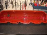
Along with the "blocked" oil filler port in the timing cover, I'm going to use a valve cover with the oil filler port and the threaded boss for the flame arrestor.

This valve cover was badly damaged during an engine pull with some significant denting. I ironed it out and then sterilized the internals, including the baffle. After that, it was glyptal'd also.

The motor I'm building will incorporate a "closed" pcv system initially, so the valve cover port will be plumbed in the appropriate manner.
 

Attachments

  • Valve Cover.jpg
    Valve Cover.jpg
    105.2 KB · Views: 1,365
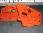
This is the inside of the spin-on type oil filter adapter, don't know if I'll use this one or the earlier style cannister oil filter.

This set has had the mating surfaces "trued". If extremely care is not used when mounting and torquing these items, they are easily warped...that results in external oil leaks that can't be stopped, and a possibility of oil bypassing the filtration system internally.

The mating surfaces on these parts were trued using 320 wet/dry sandpaper onna piece of "flat" granite.
 

Attachments

  • Oil Filter Housing and Adapter.jpg
    Oil Filter Housing and Adapter.jpg
    98.9 KB · Views: 1,368
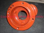
Here's the crank hub I'm gonna use, it's ready to ship down to Robert so he can machine the magnetic trigger wheel for the ignition system and mate it to the hub.

This one has a damaged section where the oil seal rides, so it will get a repair sleeve installed. Once I get the finished unit back from Robert, I'll mount the pulley and it will go with the crank and the rest of the rotating/reciprocating parts (including the fresh flywheel and clutch assembly) to the engine balance dude up in portland for completion.
 

Attachments

  • Crankshaft Hub.jpg
    Crankshaft Hub.jpg
    111.7 KB · Views: 1,391
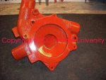
This is the front side of the water pump housing. This one was originally so nasty, a club member gave it to me because he didn't think it was useable, looked like the volute was rotted way beyond use.

After extensive hand cleaning (no abrasive blasting), the volute ended up being heavily coated with surface scale only, though it looked like concrete. Same for the interior passages.

The water pump that will mount to this housing has had it's stamped impeller custom clearanced to this volute, so this set will always be considered "matched".

These water pump housings for both I-4 and sv motors are not available as a replacement part, so we gotta do what we can to recycle this stuff for the future, do not let these go to scrap!!!
 

Attachments

  • Water pump housing.jpg
    Water pump housing.jpg
    119.2 KB · Views: 1,377
Continuing on, today I gutted the donor 152 so the block can go to the spa for a cleanup and straightening of the machined surfaces.

This is a very early '61 152 which I have intimate knowledge off over the last four years. It had set inna s80 and was only used yearly during hunting season.

A friend bought the rig, and we got it into dd service (kinda) for him. Then during a diagnostic session here in the shop, it shit the cam bearings while I watched...puked metallic bearing chunks right out of the rocker arm /shaft interface...when the dude tried to drive it home, it stuck tight. It was replaced with a later model used 152 that I freshened.

So this block is highly experienced and aged well! And it knows what "the hurt" feels like!

Along with the block, I'm using a few other parts from this one. But if the block ends up being scruud once it's cleaned and magnafluxed, then I do have two more to chose from. So let's go through the teardown...

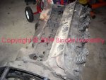
Here's a shot of a typical nazzteeazz IH motor that ain't had no luv over the years. We see these nearly every day!
 

Attachments

  • Naztee early 152.jpg
    Naztee early 152.jpg
    112.7 KB · Views: 1,337
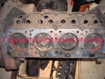
Not only was this motor dying a slow death in it's daily commute, it had a bit of a problem with coolant migrating into the cylinders.

And letting it sit in my shop on the stand non-rotated for the last three years hasn't helped any. It did rotate by hand...kinda.
 

Attachments

  • Coolant in the cylinders.jpg
    Coolant in the cylinders.jpg
    153 KB · Views: 1,352
Ain't this a purdee site??? A collage of oil/sludge, cam bearing chinks and chunks, coolant, carbon, a bolt from hell, and quite a bit of unidentifiable shit! Keep in mind, this motor was runnin' when jerked...look at the first pic in this thread and you'll see it.
 

Attachments

  • Coolant_sludge_cam bearings.jpg
    Coolant_sludge_cam bearings.jpg
    129.8 KB · Views: 1,324
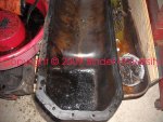
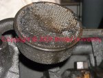
Now we're gittin' sumwheres...the oil pump intake screen is sludged as bad as any engine ive ever seen! How'd this motor lubricate??? Only by splash like a 50 year old briggs and stratton!

You think pourin' atf through the carb will clean this one up? Think replacin' the lifters will make the sludge disappear? Will moto-nu rebuild this motor for me, ya know, that piston rings and bearings inna can shit??
 

Attachments

  • Oil pump intake screen.jpg
    Oil pump intake screen.jpg
    147.8 KB · Views: 1,387
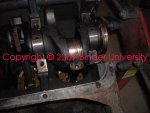
So this can be a learning experience for summa you engine-noobs, here is what we refer to in engineslangdom as a "spun bearing".

Look at crank rod journal #4 (on the right side of the pic.

When I pulled the cap off, I found the bearing shells "spun". That means that they seized to the crank journal at some point (lack of lubrication), and started turning with the journal instead of being held stationary by their "keys" and critical fit. So the bearing was "spinning" inside the rod big end. That in turn destroys the crankshaft journal.

The same thing can happen with the main bearing inserts, and most especially with the full circle cam bearings.

Whatcha see there is a pair of bearing shells that are about half the thickness they should be, only the backing remains, the actual bearing material disappeared long ago.
 

Attachments

  • Spun #4 rod bearing.jpg
    Spun #4 rod bearing.jpg
    90.2 KB · Views: 1,333
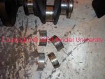
And here is the spun bearing (top) compared with a wornout (but not spun) bearing set from rod #3. Notice how the shell is all crushed and distorted. This motor was knockin' like a diesel.

All journals on this crank are badly scored. It's no use to measure it. This one will become a core now and sent to our crankshaft rebuilder. They will completely inspect and weld up as needed. The rear seal surface on this one is also fooked, so they will install a repair sleeve.

Once it's cleaned, welded as needed, and magnafluxed, it will be have the journals ground "undersize" and then cleaned again and packaged with the correct size rod and main bearings and put on the shelf for resale. I'll be using a 196 crank in this block, so the unit I have will also be sent to the supplier for a grind/micro polish.

Once the entire rotating/reciprocating assembly parts are gathered, the complete set of parts will be balanced.
 

Attachments

  • Spun rod bearing 2.jpg
    Spun rod bearing 2.jpg
    121.3 KB · Views: 1,333
here's the crank hub I'm gonna use, it's ready to ship down to Robert so he can machine the magnetic trigger wheel for the ignition system and mate it to the hub.

This one has a damaged section where the oil seal rides, so it will get a repair sleeve installed. Once I get the finished unit back from Robert, I'll mount the pulley and it will go with the crank and the rest of the rotating/reciprocating parts (including the fresh flywheel and clutch assembly) to the engine balance dude up in portland for completion.

Send that red thing down and I will do what needs dooing then send it back to ya. I will also send you the other stuff you need for sonja's deal.
 
send that red thing down and I will do what needs dooing then send it back to ya. I will also send you the other stuff you need for sonja's deal.

If them ss checks would show up like they supposed to I'll be orderin' up the mag trigger guapo and get it all in the mail to ya! In fact...I'm thinking about making a "trial install" of the mag trigger system on the runner 196 in the scoutractor now so I can get the bugs worked out!

The head I'd set aside for this build has been disassembled and is really nice! So it will be cut and gouged by dave soon and then sent out for finishing. Dave now has access to a friend's valve grinding/cutting equipment but it's still all boxed up. If we can get everything unpacked and set up, then we'll do the seat/valve cut ourselves.

I assembled a nearly virgin nine stand rocker assembly for the motor last night. I still need to rob a few more parts off another donor 152 today...I'm onna roll.

Since I have mikeesquare's crappy 196 crank on the floor now, I'm gonna drop it into the 152 block today also and check clearances for the counterweights and such. That 196 crank is much larger in the counterweight area than the 152!! More pics to come.

Dave found a 196 crank at his core supplier buddies' place a few weeks back and snaked it. It is also in bad shape. So it has gone to the crank grinder for a freshening and will be put in the ihon inventory (as a kit with bearings)...first come...first serve!
 
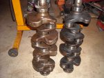
This shot compares the 196 crank on the left, with the 152 crank on the right.

The 196 has significantly greater counterweight mass. Haven't put each on the scale yet, but I'm guesstimating the 196 is about 20lbs. Heavier than the 152.
 

Attachments

  • Crank compare.jpg
    Crank compare.jpg
    464.2 KB · Views: 1,484
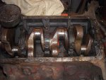
Here's a shot of the 196 crank installed in the 152 block. No issues regarding any clearances of the counterweights and the block!

Closest point of crank-to-block is 1/4".

Depending upon which rods and pistons I end up using, the replacement pistons May have to have some machine work done on the skirts for counterweight clearance...but we won't know until we have the parts on hand to test.

So Robert...I guess it's time to home in on the rod/piston combo on my end so I can finalize the plan!
 

Attachments

  • Overall clearance.jpg
    Overall clearance.jpg
    483.9 KB · Views: 1,351
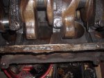
Here's a shot of the counterweight-to cylinder bore clearance, the angle here does not really show how much clearance is actually there.
 

Attachments

  • Counterweight to cylinder clearance.jpg
    Counterweight to cylinder clearance.jpg
    497.3 KB · Views: 1,370
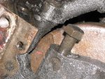
This shows the tightest clearance point...where the oil pump outlet bolts to the block...that is 1/4"+!
 

Attachments

  • Counterweight to oil pump clearance.jpg
    Counterweight to oil pump clearance.jpg
    556.9 KB · Views: 1,474
Back
Top