Rebuilding an NP202

Part 4, input cluster sub assembly.
To start off, everything gets oil (through the whole process this is true except for the rollers and grease surfaces)
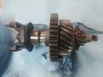
The sliding clutch washer slips on the shaft first. This provides the input drive gear a place to stop against as shown here:
20200306_103112.jpg

Then the first row of rollers are added to the gear, followed by the spacer ring, then the second row of rollers.
20200306_102459.jpg

20200306_102645.jpg

I found it easiest to set the gear on edge, like a wheel with a rag to prevent it rolling away and pass the shaft through being careful not to disturb the rollers.
20200306_103227.jpg

20200306_103242.jpg

With this portion complete the washer will hold the gear in place with the yoke end pointed upwards. The pto drive can be added, the spring washer is first added along with the brass thrust washer, take note to clock the tab for the washer into its hole in the pto gear.
20200306_104158.jpg

20200306_104822.jpg

Once assembled, hold the gears in place on the open end of the shaft and add the input shaft clutch gear:
20200306_104849.jpg

Since I wouldn't need this portion for a little while, I added the drive yoke, retaining nut and washer to keep everything together. I also wrapped it in rags to keep dust off.
The next sub assembly I did was the rear bearing retainer for the forward output shaft. Unfortunately I didn't get a picture, its not too complicated however, you simply press the needle bearing cup into the large round plate that is the front output's rear retainer.
Stand by for part 5!
 

Attachments

  • 20200306_105239.jpg
    20200306_105239.jpg
    4.5 MB · Views: 569
Part 5, front output assembly, and input cluster installation (or vise versa :crazy: )
I installed the input cluster next, if I had it to do again, I would put the front output in first, just because the case became top heavy and a bit tippy on my home made stand. The front output is very simple, so if you are following along, skip down this post to that, then do the input. (Note, one advantage of doing it the way I did, is that if you drop something into the case and have meatier arms than me (everybody) its much easier to get to without the front input installed. I could reach under the idler gear because I'm scrawny lol)
Input cluster:
Quite easy, since we already assembled it, take the yoke off, and simply pass it through the rear opening in the case, and pull the shaft through the bearing from the front OR push the SHAFT ONLY at the rear (DO NOT PUSH THE GEARS! Your rollers will disperse if you do).
20200307_124816.jpg

Next add the yoke, washer, and nut to retain the assembly together.
20200307_132111.jpg

Now the two speed shift components are added, first drop the interlock pin into its bore. It should sit between the shift bars. The idler shift bar will need to be in one of its two positions in order to allow the interlock pin to move out of the way of the two speed shifter bar. The clutch gear can be removed and fitted to the fork, wich should be prepared with the pin started in advance, then added to the case. It takes some finger gymnastics and weird angles to get it to slip in.
20200307_125007.jpg

20200307_125402.jpg

20200307_131100.jpg
20200307_131357.jpg

Once here, its pretty easy to align to drive the pin. I used the same method as the other shift fork. Move the shaft flush with the rear of the case, move the yoke all the way rearward, then drive the pin.
20200307_131518.jpg


Front Output:

Very simple, first add your gasket sealer to the rear bearing retainer and add the gasket to it. Add the front bearing retainer and two nuts to retain it, then oil up the front output and slip it into place. Add the yoke and hardware to keep it in place in the meantime. (You will have to align gear teeth manually, take care as the edges of my gear teeth were sharp) next paint the other side of the gasket with your sealer, then align the bearing in the retainer with the respective surface on the back of the output shaft. Make note of what holes are and aren't blind here. Once clocked the retainer may require seating with a rubber mallet, make sure to hit it in the center over the back of the bearing cup.
20200307_134458.jpg

20200307_142322.jpg

Now add your hardware, I put thread sealant on all the bolts, but took particular care for the open hole bolts to ensure they would seal. The others it just acts as a sort of thread adhesive. I tightened them down snug with a rachet, alternating like installing a wheel. No torque spec is given for these bolts in the manual, and I didn't make note of what I set them to, but I want to say I went around once at 30 ft-lbs then again at 35. I used the same torque setting for all the retainer bolts/nuts and where the rear output mounts to the case.
Next up, part 6, we install the rear output assembly and the last of the rollers. :icon_rotate: Just keep rollin you're almost done with the complicated part!
 
Installing the rear output isn't hard, I do want to note a few things before proceeding.
-due to my aforementioned hint at something to do with the main seals, none of the retainers have been gasketed or torqued down yet.
-in addition, the rear retainer present on my unit is worth noting for a couple reasons. Firstly, it was the odd man out for seals even though they all leaked. In fact, upon removal of the gasket, I found a gasket stain from another retainer that didn't match up with the current one. A little research later I found that the cast aluminum retainer was used to an extent on the np202 but is fairly common if not standard on the 205. At this point I'm not sure how I hadn't noticed yet, but a look in my parts manual showed a retainer that mounts a large hand drum brake. Suddenly a bunch of things began to make sense. The strangely long front e-brake cable. The odd placement of the mount for the cable near the t-case. The shoddy placement of the newer style linkage that goes between the front cable and the V shaped cable connected to the rear drums on newer axles. . . like my 1973 axles. . . Here was where it finally clicked that I likely originally had a t-case mounted e-brake.
-last note is following the previous one, I have been researching a disc brake conversion for this truck, and previously wasn't considering doing the rear for how big of a pain the parking brake seems to be. . . well, time to find a t-case mounted e-brake.

Mounting the rear output assembly isn't hard, the bore inside of the large gear contains the final set of rollers, wich are glued in place with our Lubriplate grease.
20200307_142832.jpg

Next I used the large opening to carefully look around and make sure there was no debris present inside the case, and then coated the end of the shaft with the 90wt.
20200307_142331.jpg

Next the gasket is painted onto the output housing with sealant, then the other face is painted and the unit carefully slid into place. It helps to have someone look through the pto port to stop you if you aren't aligned. This prevents you from having to reinstall the rollers repeatedly. Lastly, the threads are sealed, and all bolts torqued.
20200307_155406.jpg

Next we will address the seals and front retainers.
20190114_162807.jpg

If we have a look at our oem seal above we notice its a two in one deal. The inner side is a normal seal, wich keeps the oil in. On the outside face we have a ring of compressed felt which helps keep dirt away from the seal, in addition it will absorb the small amounts of oil that do make it past the seal. With the help of patrick r of Binder Planet, I was able to copy what he had done to recreate these seals. A second set of the seals provided in the kit is purchased, and the rubber portion removed with a sharp blade such as a box cutter or exacto knife.
20200305_163649.jpg20200305_163624.jpg
This leaves an empty meatal housing, for wich we then fabricate a felt doughnut for.
20200309_125009.jpg

This felt ring is then glued within the seal body, and pressed into the retainer after the seal. The seal is simply pushed fully down into the retainer. It is important here that when the felt portion is installed, the larger opening in the seal body faces outward in order to clear the small lip at the back of the oil slinger on the yokes. These seal assemblies stack a bit thicker than the oem and stick out a bit, wich is fine, as long as the large opening of the felt seal housing faces outward.
20200309_101256.jpg20200309_101304.jpg
20200309_122409.jpg

Once these are seated fully, the front retainers gasket thickness is determined as described in the service manual, and the gaskets are sealed to the retainer, housing, and the nuts are torqued. The rear retainer we will leave mocked up for now. Stand by for more. . .
 
20200309_123032.jpg20200309_131055.jpg
With the rear assembly mocked up, we will move to a couple other remaining details. First up, the seals of the the shift bars are pressed in.
20200309_101716.jpg20200309_101904.jpg
I found that a 3/4 inch pvc fitting was a. . . fitting tool. :frown2:
Next I figured there would be a leak present at the end of the splined shaft and yoke under the washer. So I made some thin gasket washers to seal those.
20200309_185231.jpg20200309_190544.jpg
Lastly I installed the pto port cover with the gasket with no sealant and hand tight. Just in case I need to get in there again. In addition I allocated all the hardware necessary for completion to ensure I have everything I need. 20200309_191246.jpg20200309_191011.jpg
One thing I would do differently in this process, is at this point I would remove the yokes and polish the seal surfaces. I did this later, it would've been easier at this point.
Lastly, we'll dive into the parking brake. This kit by TSM is designed for the NP205, but having that retainer, it makes a bolt on fit very easy. Here is the assembly mocked up for the first time.
20200419_111735.jpg

Now, several issues arose here, the installation of the rotor requires removal of the oil slinger, not a big deal, the yoke presses right out, however it ruined my paint in the process. :mad2:
Next up we'll detail the installation and adapting this guy to the np202.
 
20200419_111712.jpg

So, first impressions of the kit are pretty good, its good quality, has good paint, and is very user serviceable. Mocking it up to the np202 yoke revealed about 1/8" of visible runout or wobble in the rotor. Being I had a true square surface at the round end of the yoke, I clamped it up in my bench top mill and did an experiment. I faced off the ends of the flange where the U-bolts pass through.
20200418_112259.jpg

20200418_120919.jpg

Then I mounted the rotor to the front; go figure, no more runout. The areas where the nuts/lock washers go on the back of the yoke is a cast surface on my oem parts. I'm thinking the yokes of the np205 are machined, so naturally I need to machine them evenly. Should be easy. I already trued the four prongs, so setting on those surfaces and milling four notches at the same height will make it run true mounted where its supposed to be. Unfortunately my little mill didn't have enough reach. I was able to call in a favor to a friend who has a full size Bridge Port mill. He did it in less than ten minutes in exchange for a bit of yard work. Gotta love the good ol barter system.
Now the rotor has a flat even place to sit, and I got the runout to within 4 thousandths. A bit of runout isn't a bad thing here, but a full 1/8" would be straight up dangerous.
20200419_113136.jpg

Now that runout wasn't an issue I did a large scale mockup of the t-case with the e-brake caliper and all three drivelines.
20200419_130552.jpg

Here I discovered that the fancy u-joint caps in the kit don't clear the yoke on my rebuilt drivelines. With the standard U-bolt, the nut is fully threaded on all four corners without a washer, so I will torque these with red thread lock.
20200419_143313.jpg

At this point I added the shift linkage
20200419_131449.jpg20200419_133939.jpg
And lastly set up the caliper and got it oriented the way I want it, and roughly tuned in. After all seemed good, I repainted the yoke.
 

Attachments

  • 20200419_142943.jpg
    20200419_142943.jpg
    3.6 MB · Views: 529
Once almost everything was sorted with the brake, I bolted on the mounting brackets. Here I used a special cap/washer thingy for safety wire to help ensure the four main bolts wouldn't ever come out.
20200805_180945.jpg

20200805_181149.jpg

Once torqued to spec with thread sealer, the safety wire went in, with an unknown number of attempts and six or seven feet of wasted wire. . . hey, I know how to safety wire now :thumbsup:
20200805_192413.jpg

With this portion installed the crossmember is mounted, and the top two bolts torqued and sealed along with the safety wire. In addition, the bracket is bolted to the crossmember as well. Here is where I wished I had been more picky in my black paint, it didn't perform well in large surfaces and flaked around the bolt when torqued. . . guess I'll take it back off whenever I do the frame some day :winky:
20200805_205039.jpg

From here, all that was left was the flange nuts, rear retainer gasket and finalizing the brake mounting. I waited to seal the rear retainer gasket because I wanted to replace three of my bolts with longer ones to account for the e-brake bracket. Once that was all glued together, I torqued the flange nuts by locking the t-case with the e-brake adjusters. I slathered sealant on the back of the nut and the threads, and used new washers which I also backed with sealant. I sanded the back of the washer till the cotter pin hole would half align when torqued dry. Then added the sealant for perfect alignment. After that the cotter pins went in, followed by drain plugs. I left the pto port gasket for dead last just to be able to get anything dropped in there back out if necessary.

This chunk will go on a palate for now full of oil as I am planning a move. Other than installation, that's this beast wrapped. . . . wait, WHAT? I FINISHED SOMETHING? :yikes:
 
Back
Top