

You are using an out of date browser. It may not display this or other websites correctly.
You should upgrade or use an alternative browser.
You should upgrade or use an alternative browser.
Need a bit of help getting this thing firing
- Thread starter big_b16
- Start date
Michael Mayben
IHPA Tech Moderator - Retired & No Longer Online
Have you guys (not Robert) reviewed those links I posted? All the wiring, the reason behind the wiring, etc. Is in those links!
Just put the ignition system back stock. And start from that point! Stock inductive/breaker point ignition did not have a condenser mounted outside the distributor! These rigs were not broke from the factory!
If there are current feed issues with the stock wiring, then look at the bulkhead connector and verify the condition of the resistor wire if present in the oem harness and it's not been previously butchered, along with the b+ bypass feed from the starter solenoid that feeds the primary when the ignition switch is in the start position.
I've explained several times in the links I've referred you to regarding how to test a coil for primary and secondary resistance. Coil output must be checked under load and hot using a kv meter, an oscilloscope, or a coil tester. No way to do that with a dvom. The specifications you need are also given for bench testing a coil, specs are in the service manuals also.
Attached is a pic of a coil similar to the one you are scruuin' with under load onna coil tester. You are looking at approximately 32kv jumping a "air gap" of 3/4", that is a "high turn ratio/performance" coil from accel with a primary resistance of 1.6 ohms and has been running under a heavy "heat load" induced by the tester for over one hour, that is far more severe service than any ignition coil on a street-driven rig will ever see.
The only reason to use an external ballast resistor is if the oem resistor wire is nonfunc and a complete replacement wire run has been established from the ignition switch "run" position. You must not use both in series!
Any ballast resistor as well as resistor wire will get hot when in operation...it's a nichrome wire that is very similar to the element in a heat gun or electric toaster. Some sii had the resistor wire buried in the harness all the way through the end of production, even though it was not used on electronic ignition vehicles for the u.s. Market beginning some time in '75, and the harness for the gold box system is different from the harness for the prestolite electronic. These rigs were also exported and could have had no tellin' what distributor. You must do a voltage test on each wire run to determine that both the "start" and "run" feeds are proper.
And ya pop the valve cover off to watch the rocker arms on #8 to determine exactly where tdc on the compression stroke for #8 is, not the exhaust stroke! There are two "tdc" events for every complete cylinder cycle, you will have a minor compression event on the exhaust stroke as well that you can feel with a plug out.
If your primary side ignition wiring is scruud with breaker points, it's gonna be scruued with a pertronix. Ya gotta verify and fix the wiring before moving through the distributor, coil, etc.
For a point ignition system, you must have a 1.4>1.8ohm "run" feed to the coil positive terminal. The coil itself (completely disconnected) should exhibit a primary resistance when tested of between 1.4 and 1.8 ohms also. These values provide correct coil saturation for this system while providing proper current flow across the points to prevent overheating and minimize arcing/erosion, with a service life of approximately 15,000 miles.
Attachments
Last edited:
Michael Mayben
IHPA Tech Moderator - Retired & No Longer Online
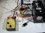
The coil is new and I checked the primary resistance before installing it and got 1.8 ohms. The reason we went to the ballast resistor is we were not getting much resistance coming from the swiched ignition wire. After work I plan on putting everything back to stock and starting from scratch and will give you an update from there. Thanks again for all the help.
Ps - it would have been a little easier to make it stock if it wasn't so screwed up to begin with!!!! Hahaha. If I would have known it was going to be this hard I would have forked over the $100 for a manual.
Ps - it would have been a little easier to make it stock if it wasn't so screwed up to begin with!!!! Hahaha. If I would have known it was going to be this hard I would have forked over the $100 for a manual.
Ok, here is the update. The ballast resistor is gone, and things are back to what I believe to be stock form. There is one wire coming out of the wiring harness going to the coil. There is no b+ wire from the starter to the coil. The resistance between the coil and where that wire terminates at the plug on the firewall is only .3 ohms. Using suggestion from rk, we have jumpered 12v to the coil and get 12v across the coil with the points closed (in run position or start since no b+ feed). Wire from ignition is shorted or opened somewhere inside the firewall, not getting any voltage to coil through ignition wire. The points are opening and closing correctly, but there seems to be a very weak spark at the plugs seen by pulling a plug and grounding it out while starting. The timing was reset with #8 at tdc on the compression stroke as described in the thread from yesterday.
Last edited:
Robert,
should the 12v jumped directly to the coil enable enough spark to fire? According to the resistance checks and voltage checks to the + and - side of the coil, it is operating properly. We don't have the equipment available to test it as per michael's suggestion to verify proper coil output. Once we get it to fire, we can go back and re-wire the ignition to include the start and run circuits from the starter/ignition switch.
should the 12v jumped directly to the coil enable enough spark to fire? According to the resistance checks and voltage checks to the + and - side of the coil, it is operating properly. We don't have the equipment available to test it as per michael's suggestion to verify proper coil output. Once we get it to fire, we can go back and re-wire the ignition to include the start and run circuits from the starter/ignition switch.
Michael Mayben
IHPA Tech Moderator - Retired & No Longer Online
Robert's not "on" right now.
Run a jumper from the battery positive terminal to the coil positive terminal. Crank the engien over and if the coil is ok and dwell is set, it will run. That's a "hot wire" setup like us oldtimer's used when pop hid our car keys.
You can run b+ directly to the coil for maybe 5>10 minutes with the engine running before the points start turning red and blue from excessive heat (current). It it stalls, disconnect the hot wire quickly or the points will undergo meltdown real quick.
Eric VanBuren
Member
Robert,
should the 12v jumped directly to the coil enable enough spark to fire? According to the resistance checks and voltage checks to the + and - side of the coil, it is operating properly. We don't have the equipment available to test it as per michael's suggestion to verify proper coil output. Once we get it to fire, we can go back and re-wire the ignition to include the start and run circuits from the starter/ignition switch.
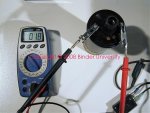
There is no need for any fancy equipment to adequtely test they coils output potential. The rough rule of thumb is 40kv an inch in free air, so establish an aprox 1/2" gap between the cap end of the coil wire and ground. Turn the engine so the points are closed attach your b+ jumper and manually open the points with a non metallic object. If it will jump the 1/2" gap then your coil has enough power to start the engine. If it won't jump the 1/2" gap reduce it and try again until you get it to jump the gap each time you open the points. A 1/4" free air gap May or May not have enough oomph to start an engine depending on the a/f mix, spark plug gap, and actual cranking cyl pressure. The ability to jump a wide spark plug gap of .050 in free air only translates to an aprox voltage of 2kv no where near enough to start any engine.
Here is a pic of my "coil tester" used professionally for over 15 years to test all types of coils, old fashion canisters, coil in cap hei honda & toyota, "e" core, waste spark and even "dumb" coil on plug units.
Attachments
I am starting to think this wiring is a real cluster. My frustration level is peaking right now. I would like to get things back to oem spec and proceed from there. Starting from the beginning is the way to go right now because I am just running in circles.
Does anyone have a wiring schematic for the ignition? When every wire in the harness is black then it makes tracing things a bit of a challenge. Also when there are wire nuts connecting the alternator to the wiring harness I am guessing they didnt take much care in making things factory. I am starting to think the ignition switch might be suspect.
Does anyone have a wiring schematic for the ignition? When every wire in the harness is black then it makes tracing things a bit of a challenge. Also when there are wire nuts connecting the alternator to the wiring harness I am guessing they didnt take much care in making things factory. I am starting to think the ignition switch might be suspect.
Last edited:
Michael Mayben
IHPA Tech Moderator - Retired & No Longer Online
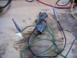
This a portion of the electrical schematic...only for the ignition system for a '79 Scout II. That's the vehicle that originally described.
The wiring for a breaker point distributor/Scout II however has nothing in common with this schematic for the most part.
Why would you spend $400+ to put a new wiring harness in and expect any better results? If you can't rig a simple "hot wire" setup to provide current to run a breaker point system, then running a harness is certainly not something you are capable of doing! That takes one wire!
Make it run now with a points distributor and coil of the proper "value". It simply cannot be any easier to do.
Attachments
if you can't rig a simple "hot wire" setup to provide current to run a breaker point system, then running a harness is certainly not something you are capable of doing!
One would think it is just that easy. But like mentioned before, with a 12v "hot wire" setup, it isn't getting the spark to fire.
Eric VanBuren
Member
one would think it is just that easy. But like mentioned before, with a 12v "hot wire" setup, it isn't getting the spark to fire.
Which is why you need to test the coils output ability as I described above. That will prove out the coil and condenser's ability to provide adequate spark. If you can't generate a spark that will jump a 3/8" free air gap like that, then the coil or condenser is bad.
Thanks eric, we're going to test that coil and see if we can get it to jump a decent gap. If not, we'll have to try an upgraded version (accel or the like). According to michael, it should be a 1.4 - 1.8 ohm primary resistance and a local store has the 8140 which is a 1.4ohm primary.
Michael Mayben
IHPA Tech Moderator - Retired & No Longer Online
Eric's redneck coil tester works fine for checking if a coil will "make a spark" at a single point in time. That can also be done using the distributor (if it is a breaker point version) in the vehicle as he pointed out.
A similar test can also be done "sometimes" regarding an electronic trigger distributor but ya better dam sure know how to do that or you will blow the electronics on an electronic ignition system. Normally that is done using a dedicated "trigger box"-type tester, though there can be redneck workarounds for that also...I have a few of those but I will not discuss that kinda stuff here as it always leads to parts damage when folks don't follow directions, then they blame me.
In the case of the various systems that IH used on sv engines, the ignition coil specs are virtually the same for all versions, whether breaker point trigger, a delco "mag pulse" trigger, a Holley gold box trigger, or a prestolite electronic trigger. That greatly simplifies stuff as "one coil fits all".
But that does not test a coil.
Testing a cannister-style coil involves several checks whether on the bench or installed onna vehicle:
1) disconnect all wires/harness from the coil, it must not be connected to anything.
2) measure the primary resistance with a dvom (follow instructions for your device), multimeter, or ohmmeter...one probe on the positive terminal, one probe on the negative terminal, polarity is not important at that point. Make the reading and record. Repeat it. Repeat it again. If ya get the same reading three times in a row, then that is the value.
3) measure the secondary resistance with the same instrument, one probe engaging the secondary terminal (center terminal on the coil in the pic), and the other probe on either the positive terminal or the secondary terminal (doesn't matter which on this type of coil). Repeat three times and record.
4) if both resistance tests are within spec (typical 1.4>1.8 ohms primary, 6.0k>9.0k ohms secondary), the coil will fire a plug with an engine running when the coil is "cold".
5) reinstall the coil and rig an additional "air gap" of approximately 1/4" between the coil wire and the secondary terminal with the engine running at idle speed. Let it run a minimum of 15 minutes or until the engine stalls or starts blubbering. If it don't blubber/stall, the coil is good under heat load running at full output potential.
If it blubbers/stalls/spark is intermittent, then the coil is removed and gets smashed with a hammer and discarded as ng so it can't be mistakenly re-used.
A cannister coil like is used on most all oem automotive apps up to the advent of the "e-core" coil design will normally fail only after running under load (which means it gets hot internally) for a period of time and performance begins to diminish to the point it can't produce output for all cylinders as designed. Some mechanics refer to that as a "coil breakdown"...random misfire, then steady misfire, then no spark at all or too weak to ionize the plug gap under cylinder pressure.
The yellow accel coil in the tester picture I posted shows excellent output, and I know what it's max output is in kv because it was also tested before hand on an engine analyzer w/oscilloscope. In that pic, the coil is cold.
That coil tester has a heat position which is then engaged for five minutes, after which the test is repeated. That is not long enough on most "high turn" coils to create heat load to test the coil under engine operating conditions. So I heat for at least 30 minutes, checking output periodically.
The accel coil in the pic begins to break down at 12 minutes (yes this failure point is repeatable), output kv is reduced by approximately one half in free air. That means the coil will not fire a plug under compression load in a cylinder when dosed with the intake charge "mix"...yet it still sparks on the tester. You can also hear the spark output begin to deteriorate.
At 20 minutes output kv goes away completely...the coil is now dead and useless. Primary resistance test show "open circuit/winding". Let it sit three hours and guess what...it comes back to life and the cycle begins again...day after day after day!
So yes...that yellow coil tested "good"...but it ain't worth shit. Why???? Because all the insulating oil leaked out though the shittee "seal" found under the secondary female terminal. But that is just one of several failure modes that a cannister-type coil can develop.
The accel 8140 has a 9.2 k-ohm secondary, will the extra 200ohms have much of an effect? I was unable to find an accel that spec'd to 1.6 ohms like michael's, the closest I could find was the 1.4 ohm one (they also had a 0.7 ohm line).
Does anyone have an actual part number for the points that should be in the Holley distributor...or better yet, a picture? I don't know if it matters, but we're just matching what was in there...and we're not very confident the po cared about compatibility.
Does anyone have an actual part number for the points that should be in the Holley distributor...or better yet, a picture? I don't know if it matters, but we're just matching what was in there...and we're not very confident the po cared about compatibility.
Last edited:
Michael Mayben
IHPA Tech Moderator - Retired & No Longer Online
Any coil with a primary resistance of between 1.4 and 1.8ohms is fine, the secondary resistance is only a function of "turn ratio" and that has nothing to do with what you are playing with as long secondary winding is not open or is not down below about 4kohms.
Pull the points out, clean and lay on the bench with no condenser connected. The points are simply a switch. Resistance across the point set should be under 2 ohms, the lower the better but will never read "zero" as any point set will exhibit a nominal resistance of at least 0.2 ohms.
Pull the points out, clean and lay on the bench with no condenser connected. The points are simply a switch. Resistance across the point set should be under 2 ohms, the lower the better but will never read "zero" as any point set will exhibit a nominal resistance of at least 0.2 ohms.
Eric VanBuren
Member
the accel 8140 has a 9.2 k-ohm secondary, will the extra 200ohms have much of an effect? I was unable to find an accel that spec'd to 1.6 ohms like michael's, the closest I could find was the 1.4 ohm one (they also had a 0.7 ohm line).
Does anyone have an actual part number for the points that should be in the Holley distributor...or better yet, a picture? I don't know if it matters, but we're just matching what was in there...and we're not very confident the po cared about compatibility.
The curved and straight Holley points are very different and you can't bolt the wrong set in.
Holley straight points
http://www.partsamerica.com/productdetail.aspx?mfrcode=nie&mfrpartnumber=ff3h&parttype=199&ptset=a
Which if you click the see all vehicles this fits you will see they are the same as 6cyl fords
Holley curved points
http://www.partsamerica.com/productdetail.aspx?mfrcode=nie&mfrpartnumber=ih5&parttype=199&ptset=a
Which are an IH only part.
In case someone tried to get creative the prestolite
http://www.partsamerica.com/productdetail.aspx?mfrcode=nie&mfrpartnumber=ih6&parttype=199&ptset=a
And the delco in their non uni-point version
http://www.partsamerica.com/productdetail.aspx?mfrcode=nie&mfrpartnumber=dr8hv&parttype=199&ptset=a
Yep, those are the points we've got. Tested the original coil and it couldn't jump a 1/8" gap. We installed the accel coil and got it to easily jump a 1/2" gap. Reinstalled the points, condenser, and the new coil and are getting much stronger spark at the plugs. Installed new plugs, old ones were pretty fouled. Verified timing w/o valve covers on and it matched with the timing Mark on balancer and location of piston. However, it still won't fire. Point are opening and closing like they should and air gap is at 0.016". Still using a dedicated 12v jumped wire straight from battery. Points have 0.4 ohm resistance. Are their any checks to make sure the condenser is correct? We've got bwd's g111 condenser, which comes up as one for this engine on the partsamerica website listed above.
Last edited: