Hot Wires

Caperodder

Member
Hi folks,

new to this particular forum. Been working behind the scenes on some carb issues with the most excellent mr. Mayben. Needless to say...those problems are solved!

Thought I'd start posting so that others experiencing similar issues can follow along.

The vehicle in question is a 1972 Scout II 304, 4 speed, stock.

Ordered a rebuilt distributor last week from rock, as my vacuum diaphram is full of holes, and the dwell wanders just a little bit. While I'm waiting for that unit to come in, I observed that the wire harness going from the bulkhead to the coil, (white and green), gets so hot, it can't be touched. Even stranger, the wire will cool right down again after the Scout has been running for a short time. I'll be measuring the white, ballast wire's resistance in just a bit.

Question is this. Should it get hot or should I assume a short? My understanding is that the ballast wire is not used on startup so that a full 12v is applied to the points, then drops down to ~9v, using the ballast wire, to keep the points from burning up. Not sure if this is a correct assumtion. Second question is; before I start yanking on that bulkhad connector, does it just pull straight out? Where does the other end of the ballast wire terminate? Ground? Inside the cab?

Also, hating this type of connector like everyone else, has anyone replaced it? I was thinking of crimping on a military type, (round threaded), connector.

Thanks much,

brett
 
Dang, I thought I was gittin' some long distance carb skoolin' from mayben, but he's only about 3 hours from me. He recently helped me revive a tempermental 4150 via phone and email. It plays real nice now. I don't know the answers to all your questions, but I can shed some light on a few. No doubt mm will be able to address each one and won't hesitate to cyber-slap me if I mis-inform you. Your understandling of the resistance function during startup and then run is correct. The bulkhead connector basically just pulls out like you say, but May need some side to side wiggle to achieve seperation. The resistance wire supplies voltage to the coil when the key is in run/on position, so it doesn't terminate as a ground. So it either terminates at the ignition switch or the fuse block.
 
And both of ya are correctamundo! But the "hot wires" title got me going! We're working with another member of the fwb mafia down in medford that is running a dui distributor with the "hot wires" setup!

Brett... Trever has been going through nearly the same ignition stuff for the last few weeks as you, but his issue was related to installing the wrong ignition coil...and he was trying to work out some detailed carb tweeking issues when the real problem was ignition. Well not quite...his first carb rebuild was a real learning experience compounded by the ignition issues!

The resistance wire originates at the ignition switch "on" position. Total oem length of that wire run is 58" which provides 1.8ohms resistance (nominal) at 70*f, that is a stranded "ni-chrome" type wire with a fiberglas overbraid for heat protection. It does get very hot when the engine is running, it has to!! In fact, due to the really crappy way IH incorporated that wire run into the loom, it is very common that it actually burns in two, and takes out adjacent wire runs in the bundle also! That wire should have never been put up into a loom/bundle!

To make it worse, the wire is doubled back on itself, sometimes twice in the harness. The point where it's folded back results inna tight crimp which breaks through the insulation resulting in an extreme concentration of heat.

Add in that design deficiency, along with the absolute worst type/quality of oem bulkhead connectors known to the industry, ya got electrical issues that came right from the factory as standard equipment!

The 1.8ohm "run" feed to the coil, plus an internal primary resistance in the coil itself, provides a "saturation" current of a nominal 3.2amps at idle on the breaker point ignition. That current factor is also dependent upon the distributor dwell setting. This current factor is intermittently switched of course by the breaker points, or in the case of trever's distributor setup (delco) by the crane xr-I replacement module. Same thing holds true for a pertronix conversion (a pertronix II module is a slightly different animal).

The key factor here is the use of a coil with a primary resistance of between 1.4 ohms and 1.8 ohms for the sv (eight cylinder) ignition system. In other words, a coil with a "stock" specification on the primary circuit winding.

This whole issue of "coil resistance", ballast resistor, etc. Is grossly misunderstood and that kinda bsstuff is then compounded by regurgitation by folks who don't have a clue as to how this stuff works! And then the marketing bullshit form the ignition component manufacturers/suppliers takes over which really confuses things! We'll deal with this whole subject in another thread so it can be addressed separately!

Trever saw some of this type "info" demonstrated at the Binder Bee on various rigs we ran on the engine analyzer, nearly every vehicle had some kinda "dwell" issue, even the one's using a pertronix!

Inna re-wire operation, the resistor wire can/should be eliminated, unless we're talking a total restoration where originality is important. Simply substitute an external-mount ballast resistor of the proper value...1.4>1.8 ohms! And this holds true only if the entire ignition system being used calls for a "ballasted" feed to the coil on the run circuit. Many of the electronic conversions do not use a ballasted feed, so there is no general rule of thumb about this, each system needs to be looked at as a complete system, not just a component swap. Many of the "upgrade" components are not compatible with each other, contrary to what the various manufacturers May claim or allude to!

And I'm not talking about ignition systems which communicate bi-directionally with an ecu as used in some efi/electric carburetor apps. Those are a complete separate issue!

All the above is based upon an sv application, the exact same principles apply for any 6 cylinder or 4 cylinder system. However, the resistance wire May be supplemented by inclusion of an additional ballast resistor and a coil with a different primary winding resistance factor, along with a different dwell factor...all of which determines coil saturation and primary circuit current draw for the individual system being serviced. There is no single wiring/resistance setup that is correct for all inductive/kettering ignition systems!

As for the bulkhead connector re-work...I personally do not like or use 'em! A terminal strip/barrier strip of the proper quality and ampacity is a far superior! Bulkhead connectors are/were only designed for an assembly line process. Mil-spec, secure gang connectors are certainly nice, but can be a pita to install if the existing wire runs are cramped for length/space.

If your bulkhead connectors dont' simply pull out, then that is because the male/female contacts inside the connectors have fused/deteriorated due to the fact they are not of the correct ampacity value for the circuit!! The poor connection intro'd voltage drop and extreme heat buildup resulted over time. I'm sure you will find 'em badly damaged! That 10 gauge wire run with the "screw-on" terminals is the main feed through the ammeter, which then supplies the fuse distribution system and is the charging feed to the battery (ultimately). The ammeter "feed" is a great design, but was simply poorly integrated by ihc electrical system non-engineering! I would never eliminate that system, but simply upgrade it to high quality componentry. And add a voltmeter to the system at the same time for total charging system monitoring.

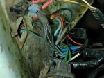
Attached is a pic of an early sii with possibly the worst botchjob on one of the bulkhead connectors that I've delt with in recent history!!! A large portion of the resistor wire had been taken out and a piece of 20 gauge (!!!!) spliced in with scotchloks! And ya can see the 10 gauge main feed has been butchered too! This one had a resistor wire circuit meltdown right in my parking lot and actually caught fire while we were bs'n over the open hood!

All of this was delt with in a very "poorboy" (but safe) manner so that the owner could make it home. I simply installed a proper "used" resistor wire I had on hand stripped out of a melted wiring harness (I don't throw anything away!), and re-worked all the real trashy splices that had been done over the years. You can see that many po's had tried to bypass the bulkhead connector over time. This one is a prime candidate for a total re-wire! Ya should see the reat of the story!
 

Attachments

  • Botched Bulkhead.jpg
    Botched Bulkhead.jpg
    425.8 KB · Views: 901
Last edited:
Damn! I had to read that one a couple of times! Thanks to both of you guys for responding.

Just did a bad thing. Broke a rule that says "if it aint broke, don't fix it. Went to loosten the nut on my coil, and it just sheared off, rendering this coil, (original IH), garbage. Oh well, as long as it's off, I can check the ballast wire, although from reading your response, probably has nothing wrong with it. Supposed to get hot.

Ok. Need a coil with stock specs. Any suggestions for a napa replacement.

Man I'm pissed just now. At least it's in the garage.

Brett
 
I thought you was goin' ta new jack city this weekend brett!

Here's my standard list of oem coil replacements:

wells c819, 1.8 ohm primary interchange:
standard uc12
niehoff dr178
napa echlin ic12
borg warner e30
gp sorenson gc300

all are "oil-filled" that's the only way these types of coils are manufactured. I'd be very surprised if all did not say "hecho in mexico" on 'em, nuthin' wrong with that, ya ain't gotta choice!

All will most likely have "use with external resistor" stamped on 'em also. That single statement is what causes so much confusion and misinformation about this stuff!

The accel, msd, pertronix, mallory, etc. Aftermarket "performance" coils are gonna be exactly the same thing, only some of those (not all ) have a higher "turn ratio" count which theoretically can provide a higher "voltage available" if engine firing conditions demand it.

This same issue is what bit trever's butt a few weeks back, he got my standard lecture and a buncha henscratched "specs" at the Binder Bee for his breakfast!
 
One more tidbit...since I threw out some numbers regarding resistance, current, voltage, etc. I didn't mention "ohm's law" which works fine on paper...but will kick yore butt when the motor is runnin'!!

We refer to these systems as "12 volt dc" based. They are not!!!!

Actual operational voltage is whatever the alternator (or generator) is producing to the battery at any point in time that current/voltage is being measured. That can be between a nominal 10.5vdc and as high as 14.8vdc+, and is also dependent upon total electrical system "load", battery state of charge, and engine/alternator rpm.

So when talkin' an inductive-design ignition system, all the variables come into play, you do not use "12vdc" as a standard, you use whatever the real numbers are as measured with test instruments. You can see exactly what the primary current is in that circuit by inserting an dvom with at least a 10amp setting/capacity inline with the coil negative terminal to the distributor breaker points. At cranking speed you will see around 4.5>5.5 amps, once the motor settles into a fast idle, prolly around 3.8>4.0 amps, then once the engine is in stable idle, a nominal 3.5amps. A "hall effect" electronic trigger will show around 2.5>3.0 amps when used to trigger an inductive system.

If a cd "box" (capacitive discharge) like an msd 6 series, a mallory 6 series, etc. Is added, then primary voltage is transformed to 420vdc>580vdc and primary current goes up accordingly. That is why all those components must be matched in order to prevent frying either the coil, the box, or the trigger! Each "system" will have it's own unique electrical characteristics, and I've not tested/recorded data on all possible combos...but I'm working on it!

By the way, a delco remy hei (or it's clones) is an inductive system, not a cd system!
 
Ok brett...I see an hei distributor in yore bowtie motor in the '32 rollin' chassis! Looks like an accel cap on it, maybe an accel distributor?

So don't confuse ignition "specs" and "how-to's" for that one with yore Scout II stuff, it's a somewhat different animal! No "ballast" or "resistor wire" involved with that one, the module inside takes care of all the hocus-pocus! It needs only a straight 12 gauge b+ feed from the ignition switch, I like to use 12 gauge so no voltage drop is introduced.

Reason this is timely? Trever is also working with another fwb in his 'hood with an sii/sv motor runnin' a dui version of an hei inductive system. And this same confusion came up last Saturday for them!
 
Ok. Thanks again for the in-depth lesson. Just picked up the echlin ic12. Hecho en mexico, of course. Bought an ohm meter with me just to check it out. Guy at the desk "assures" me, and "trust me", that there will be no resistance between +/-.....he was wrong.

She's all installed and up and running, which is nice cuz I wanted to take er out on sandy neck tonight. Blues and stripers are running like crazy.

I "escaped from ny". Wife is there visiting, so I guess I'll just have to go fishin.

As long as I'm breaking things, I pulled the headlight switch out. No headlights last night. Not sure yet if its the switch or the bulkhead connector. Parking lights work ok but the high beam indicatior light comes on.....looks like more fun ahead. As long as its out, I'm going to bypass the instrument pot.

Thanks for the help!

Brett
 
Well he was a knowledgeable counter ape wasn't he? Very good show on your part by taking the dvom with you. Man I love me some good blues music and I'll always have a soft spot in my heart for strippers...oh wait, we're not talking about the same things, are we?
With regards to your headlights, check the fuse panel first. The voltage for the headlights passes thru the floor mounted hi/lo dimmer switch. After many years of service, those switches often fail which can leave a feller with only low beams or high beams, but not both. I know that's not exactly your symptom, but it would still be a good thing to check. Aren't these old rigs with their multitude of electrical gremlins and po hatchet jobs just great?
 
Looks like the floor h/l switch checks out ok. I'm starting to suspect the light switch itself. Only because everytime I fiddle with it I get a different effect. Headlights never come on, sometimes the hi-beam indicator comes on with the parking lights sometimes not. Sometimes I can switch the interior lights on, sometimes not. Parking lights, directionals, brake lights all work fine.

Dunno, got some more work to do here. Headlights are kinda nice to have.

Brett
 
Ok brett...I'll train trev in how to I.d. A bluefish vs. A brown trout! I always tell 'em apart by the smell! And the fact that blues are close family members to wolves, only they got scales insteada hair.

Believe it or not (and this has got nuthin' to do with makin' sparks!) I ate my first stripah when visiting ihon this past April! Jeff's pop caught several in the American river! I'd have to say...just as tastee as pacific halibut or sturgeon!

Scruu this junkiron talk...I'm goin' fishin'! There's still some steelhead in the front yard!

Here's a pic of kathy with her firstever landed blue onna bogagrip. Ya don"t git yore hands anywhere close to a blue! They are like 'cudas that stink! I know it's a spinnin' rig. I had her flyrod up front riggin' a steel leader after we got tired of loosing clousers and she couldn't wait for me to finish. That's r.j. Sylvester (guide) and we're driftin' off the south side of monomy island.
 

Attachments

  • KS Blue.jpg
    KS Blue.jpg
    63.2 KB · Views: 796
Fwiw

I had a GM / delco dimmer switch fail and it left me with no headlights -- no low or high beams....:icon_eek:

did you test the dimmer switch by "jumping" the connector?

In my case, it was obvious the switch was broken -- it did not "work correctly" when you depressed it.

It May be the headlight switch -- iirc, I think the GM version has a circuit breaker in it to "protect" the headlights / wiring.
 
Well....I can see where this thread is going. Problem is, no headlights no night fishin on the beach.

The reostat is already shot on the switch, so I'll just pick one up this week.

Got seven stiches in my thumb several years ago by my friend the blue! Picked up two little ones this morning on an atoms popper.

Brett
 
Well,

let me just finish off this thread in regard to the headlights. Turns out there was no ground to the headlight connector. Traced it back to the ground source, which attaches to the screw that holds down the horn relay. Took a while to trace, but everything now works fine.

Thanks,

brett
 
Great, glad you figured it out and let us know. I (at least) learned something new. I am not good at tracing electrical issues -- fortunately, I have not had to do it much :gringrin:
 
Back
Top