I have a 1978 Scout II with a 1977 345 engine (original 304 blew and was replaced with 345). I have a Prestolite distributor with a Petronix electronic ignition in it right now and would like to change to a points style distributor. I’m not sure if that’s stock or if it was added by the previous owner. I thought I had read in another thread that they stopped using points style distributors in 1974. If not, and the previous owner added the Petronix, can I buy the parts and change it back to points? Or can I just buy a new Prestolite points style and swap it out? Just not sure what is compatible. Thanks for any assistance!


You are using an out of date browser. It may not display this or other websites correctly.
You should upgrade or use an alternative browser.
You should upgrade or use an alternative browser.
Change 1977 345 to Prestolite points distributor?
- Thread starter mbiver
- Start date
Winchested
Active member
The later prestolites were an all electronic hall effect pick up, they were never points.
Winchested
Active member
Don't understand why you would the prestolites are world's better than the points style ever were.
If you went back to a points style you'd have to change out the coil and put in a condesor as well that matches the dist.
If you went back to a points style you'd have to change out the coil and put in a condesor as well that matches the dist.
Thanks again. I called in and chatted with the team from IHPartsAmerica. Very helpful! After discussing, I went ahead and ordered up a used Holley points distributor, points style coil, condenser, rotor, premium cap, points, vacuum advance, and wires from the IHPartsAmerica store. Sounds like the Holley should be compatible with my 345. Just need to put it all together.

Scoutboy74
Moderator
Yes it should. Just curious as well about the why? Was something not working with your present setup?
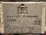
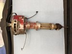
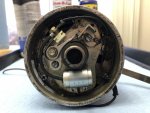
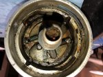
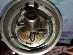
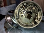
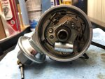
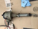
Thanks for confirming compatibility, Scoutboy74. My Prestolite with electronic ignition is working just ok. Honestly, though, I want a working points style setup on hand so the Scout can be my EMP bug out vehicle.  I just got the "new" Holley from Jeff and team at IHPartsAmerica and have attached pictures. Needed a little cleaning, but so far so good. I did have a question about the condenser. Does it have to be inside the distributor? It's a really tight fit in there. I've seen them mounted to the side of the coil and was wondering if pulling it out and placing on the coil has the same effect?
I just got the "new" Holley from Jeff and team at IHPartsAmerica and have attached pictures. Needed a little cleaning, but so far so good. I did have a question about the condenser. Does it have to be inside the distributor? It's a really tight fit in there. I've seen them mounted to the side of the coil and was wondering if pulling it out and placing on the coil has the same effect?Attachments
-
 20190331_031004093_iOS.jpg55.2 KB · Views: 613
 -
 20190331_004630140_iOS.jpg56.9 KB · Views: 618
 -
 20190331_004731826_iOS.jpg66.6 KB · Views: 675
 -
 20190331_013726460_iOS.jpg94.8 KB · Views: 642
 -
 20190331_030438711_iOS.jpg73.4 KB · Views: 575
 -
 20190331_043541322_iOS.jpg85.4 KB · Views: 646
 -
 20190331_044722274_iOS.jpg73.4 KB · Views: 770
Scoutboy74
Moderator
Yes, the condenser for the points always mounts inside the distributor. The item you've seen attached to some coils is a noise suppression capacitor meant to eliminate the interference heard through the MyT Fyne, AM sound system while the engine is running. Not as essential these days with quality insulated spark plug wires.
Do you know about the resistance requirements for protecting the points and coil?
Do you know about the resistance requirements for protecting the points and coil?
This is the first distributor I’ve ever set up so I definitely don’t know about resistance for the points and coil. I’d be interested in any setup information you could provide. The distributor has a single black wire coming out of it. Is that the hot line and connect to the positive terminal on the coil? Also, the wire is cracked and kind of brittle. Can I just replace it with any new wire as long as I plug the hole in the side of the dizzy? Or is there an official replacement wire that has the plug for the hole integrated like the original? Part of the reason I wanted to attempt this setup was also to educate myself, so any knowledge you can pass on is appreciated. Thanks!
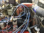
Here’s my current setup with the Prestolite and Petronix. There is a tachometer wire as well. I didn’t set this up and have no idea if it’s correct. The original 304 was blown 2 days after purchase from a used car lot many years ago. We came to an agreement that if I paid for a new engine, they would do the install for free. I found the current 345 in a junkyard for $200 and they installed it. Though I don’t know much about mechanics now, I knew next to nothing then so really don’t know if it was setup right or if the current dizzy was on the 304 or came with the 345. It did seem to run well at the time. Since I want to go to the Holley points setup anyway, I guess I’m just looking for the full correct setup and am willing to purchase whatever I’m missing from Jeff and team to make sure it’s done right and I learn the correct way.
Attachments
-
 78BD0F59-834B-458E-B748-F6BB11409D35.jpg96.8 KB · Views: 634
 -
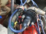 AD6DD813-4379-4A02-B021-0CAF88E5944C.jpg82.5 KB · Views: 709
 -
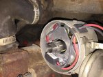 056289ED-3506-439C-B551-1FFE5937498C.jpg82.2 KB · Views: 605
 -
 29BC0015-8A43-44A3-AE09-CB9FE50868FE.jpg66.2 KB · Views: 648
 -
 7AF58513-E1AD-4B9E-9C71-2895DBF6E29E.jpg64.4 KB · Views: 623
Scoutboy74
Moderator
The single wire coming out of the distributor goes to the coil NEGATIVE terminal. The tach feed will also go there.
Breaker points will over heat and eventually burn out if they are subjected to full battery voltage for very long. This wasn't a concern with your Prestolite setup.
You first need to determine which of the wires hooked to your Presto POSITIVE terminal is the switched feed from your key. It will be energized in key ON and START positions. You'll need to get yourself a cheap, illuminating test probe with gator ground clip if you don't already have one. Use the probe to test the loose wire terminations until you isolate the switched feed wire. Label it so you don't forget.
Next thing you should add to your tool arsenal if you don't already have one, is a handheld multi-meter capable of measuring resistance in Ohms. Set it to the lowest end of the scale. Then probe across the coil POS and NEG terminals. You should get a reading of 1.x Ohms primary resistance. Now, subtract that reading from 3.3. The remainder will be the value of ceramic ballast resistor that you will need to purchase from an auto parts store. For instance, let's say your coil measures 1.5 ohms across the terminals. That would leave you needing a 1.8 ohm ballast resistor to make up the difference. The Primary resistance of the coil, plus the ballast resistor to make the proper total resistance, will reduce the voltage to the coil and the points enough to protect them from overheating. But we shouldn't assume your coil primary resistance is what it needs to be. Measuring is the way.
Once you've determined your coil primary resistance and purchased a ceramic ballast resistor with the right value to get you slightly above 3 ohms total resistance, you'll need to mount the resistor to the firewall where it can be reached by the wire that you previously identified as the switched feed. Trace that wire back to the bulkhead connector at the firewall. Then run a few inches of the wire over to the ballast resistor. Cut the wire and affix a termination that will allow you to connect it to the nearest side of the ballast resistor. Affix the same type of termination to the other loose end of the wire where you clipped it in two. Attach that end to the other side of the ballast resistor. What you've done is interrupt the switched feed wire with the ballast resistor. In other words, the switched feed voltage should now pass through the ballast resistor on it's way to the coil.
Scouts older than yours that came originally equipped with points distributors, used a special resistor wire of a specific length to provide not only the switched feed to the coil, but also serve as the ballast resistor. Your Scout doesn't have this resistor wire, just a normal wire. That's why you need the ceramic ballast resistor instead, to complete your points distributor retrofit.
Now, you may find once you've done all this, that your engine will occasionally have some difficulty lighting off during that initial cold start of the day, especially during colder times of the year. To combat this, you'll want to run a new length of 14 gauge wire from the starter solenoid 'R' terminal, which you can either run up to the coil side of the ballast resistor, or all the way to the coil POS terminal. Either way, the choice is yours. This wire will be a momentary ballast resistor bypass feed. What it will do is allow full battery voltage to reach your coil only while you are starter cranking. Once the engine lights off and you release the key from START to ON, the ballast resistor feed will take over, once again providing a reduced current to your coil while the engine is running. So that will mean you have two switched power feeds to the coil. One for starter cranking and one for engine running.
Breaker points will over heat and eventually burn out if they are subjected to full battery voltage for very long. This wasn't a concern with your Prestolite setup.
You first need to determine which of the wires hooked to your Presto POSITIVE terminal is the switched feed from your key. It will be energized in key ON and START positions. You'll need to get yourself a cheap, illuminating test probe with gator ground clip if you don't already have one. Use the probe to test the loose wire terminations until you isolate the switched feed wire. Label it so you don't forget.
Next thing you should add to your tool arsenal if you don't already have one, is a handheld multi-meter capable of measuring resistance in Ohms. Set it to the lowest end of the scale. Then probe across the coil POS and NEG terminals. You should get a reading of 1.x Ohms primary resistance. Now, subtract that reading from 3.3. The remainder will be the value of ceramic ballast resistor that you will need to purchase from an auto parts store. For instance, let's say your coil measures 1.5 ohms across the terminals. That would leave you needing a 1.8 ohm ballast resistor to make up the difference. The Primary resistance of the coil, plus the ballast resistor to make the proper total resistance, will reduce the voltage to the coil and the points enough to protect them from overheating. But we shouldn't assume your coil primary resistance is what it needs to be. Measuring is the way.
Once you've determined your coil primary resistance and purchased a ceramic ballast resistor with the right value to get you slightly above 3 ohms total resistance, you'll need to mount the resistor to the firewall where it can be reached by the wire that you previously identified as the switched feed. Trace that wire back to the bulkhead connector at the firewall. Then run a few inches of the wire over to the ballast resistor. Cut the wire and affix a termination that will allow you to connect it to the nearest side of the ballast resistor. Affix the same type of termination to the other loose end of the wire where you clipped it in two. Attach that end to the other side of the ballast resistor. What you've done is interrupt the switched feed wire with the ballast resistor. In other words, the switched feed voltage should now pass through the ballast resistor on it's way to the coil.
Scouts older than yours that came originally equipped with points distributors, used a special resistor wire of a specific length to provide not only the switched feed to the coil, but also serve as the ballast resistor. Your Scout doesn't have this resistor wire, just a normal wire. That's why you need the ceramic ballast resistor instead, to complete your points distributor retrofit.
Now, you may find once you've done all this, that your engine will occasionally have some difficulty lighting off during that initial cold start of the day, especially during colder times of the year. To combat this, you'll want to run a new length of 14 gauge wire from the starter solenoid 'R' terminal, which you can either run up to the coil side of the ballast resistor, or all the way to the coil POS terminal. Either way, the choice is yours. This wire will be a momentary ballast resistor bypass feed. What it will do is allow full battery voltage to reach your coil only while you are starter cranking. Once the engine lights off and you release the key from START to ON, the ballast resistor feed will take over, once again providing a reduced current to your coil while the engine is running. So that will mean you have two switched power feeds to the coil. One for starter cranking and one for engine running.
Last edited:
Thanks a lot, Scoutboy74. Got my dwell/multimeter last night and will start looking at the wires. Might take some time, though, since I’ll be moving in the next couple weeks and not sure how much I want to tear apart. Probably wait until after the move since it does run now and I don’t want to have to pay for a tow.
Scoutboy74
Moderator
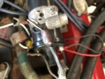
That isn't the original connector. The factory used ring/eyelet terminals for those wires, not prong terminals.
Last edited:
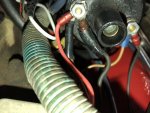
Alrighty, I’ve got it setup just about exactly as you specified. The coil from Jeff and team was 1.5 Ohms so I got a ballast resistor of 1.82 that I’m running the switched feed through to the positive side of the coil. I cleaned up the “new” Holley points dizzy, set the gap, and installed per Mr Maybens instructions. The one thing I’m not really clear about, is which of the terminals on the starter is the “R” terminal. I consulted my service manuals and it wasn’t clear. It gets pretty cold here, so definitely want to setup the bypass wire you mentioned for cold starts. Thanks!
Scoutboy74
Moderator
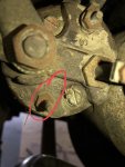
Top terminal is S for start, bottom terminal is R for resistor. Other end can either go all the way to coil POS or just to the coil side of the ballast, whichever you prefer.

Scoutboy74
Moderator
That's it. No fear of fire by hooking to the wrong one. You just wouldn't get the benefit. I'd give all those terminals some love. They look pretty crusty. Do it with your battery unhooked though.
I installed the "new" Holley points distributor per Mr. Maybens instructions and am seeing some strange behavior. I reinstalled the Prestolite w/Ptron that was in there and am seeing the same thing there as well. If I follow the timing guidance on the valve cover that says TDC at 650-700 rpms (timed off of #8), it runs terrible and doesn't have any power just pulling away from a stop sign. If I set it to 26 degrees before TDC, it runs way better. Not perfect, but doesn't have a problem pulling away from stop signs. This engine is not the original and was installed at a used car dealership many years ago after the 304 blew. I'm wondering if they didn't set it up right (is it possible the harmonic balancer is in the wrong place), or if I'm doing something wrong? (my guess) Any thoughts appreciated, thanks.
Scoutboy74
Moderator
Something's not right. Zero TDC is a recommended starting point that is generally good enough to drive on, however many of these engines do benefit from some timing advance. Usually no more than 10-12 degrees. 26 is way too much.
I gathered from earlier posts in this thread, that your Scout was a satisfactory runner/driver before you embarked on this latest distributor swaperoo. Is that correct?
Are you absolutely certain that you had the #8 piston at TDC on the COMPRESSION stroke when you did your distributor stab? This is vital. #8 piston will be at the top on the exhaust stroke too.
Are you certain you got all of your plug wires routed correctly, in clockwise fashion and according to the engine firing order beginning with #8 and ending with #1?
You might just have all of your plug wires one spot off from where they should be. I'm thinking maybe if you relocated them all one spot counter-clockwise from where they are now, you could then rotate the distributor clockwise to retard.
I gathered from earlier posts in this thread, that your Scout was a satisfactory runner/driver before you embarked on this latest distributor swaperoo. Is that correct?
Are you absolutely certain that you had the #8 piston at TDC on the COMPRESSION stroke when you did your distributor stab? This is vital. #8 piston will be at the top on the exhaust stroke too.
Are you certain you got all of your plug wires routed correctly, in clockwise fashion and according to the engine firing order beginning with #8 and ending with #1?
You might just have all of your plug wires one spot off from where they should be. I'm thinking maybe if you relocated them all one spot counter-clockwise from where they are now, you could then rotate the distributor clockwise to retard.
Winchested
Active member
Or he isn't plugging the vac advance to set his base timing.
Well, was doing some more reading and may have stumbled across the problem....ME! I was NOT verifying that it was the compression stroke....just that there was pressure pushing back against my finger in the number 8 spark plug hole. So I could have been at the top after the power stroke, instead of where I should be...at the top of the compression stroke. Hope I haven't done any damage. I've got the exhaust manifolds off now soaking in some rust remover and will re-stab the distributor once I've got those painted up and back on....this time on the compression stroke.
Scoutboy74
Moderator
That's how you know you're on the comp stroke is by the air forced out of the vacant plug hole. If the piston was then at the top of the stroke as correlated by a piece of dowel rod or screwdriver to indicate peak upward travel, in combination with seeing the timing scribe very near 0 on the index, then that piston is at TDC on the comp stroke. From there it comes down to how far the distributor gear may have rotated as the distributor was inserted, and how closely aligned the rotor was under one of the holes on the distributor cap. That would be where the #8 plug wires goes.