Cam/Valvetrain Issues

cheese1

Member
I posted in the past about a rebuilt 304 I picked up that sat for 10 years and was never installed.
After installing the motor following proper break in procedure it developed a rapping noise in the #1 exhaust lifter after 3 hours run time that would not go away. After further inspection 12 of the 16 lifters were not rotating and figured that the lifters were used ones put in by the builder. I put a new clevite stock cam and sealed power lifters in and everything was fine. No ticking or rapping noises and all lifters were rotating. I've put close to a 1000 miles on the motor with no issues. Now it's making the rapping noise again. Only this time it sounds like it is coming from the #2 cylinder. It raps loud during start up for about 5 minutes. Only when the motor temp is hitting 150 degrees does it start going away. When the temp hits 180 the noise is almost non existant. You can hear a faint noise when the rpm's increase. I pulled the rocker shaft this weekend to check things out. I pulled each lifter and none were cupped. I did notice that on the #2 and #6 exhaust valves tips that the tips had a rough edge with small amounts of material that were wearing off the edges. Also #2 and #6 exhaust lifters are not rotating. Oil pressure is 50# at start up and 10# when hot. Lot's of oil flowing through the boat style rockers. The motor runs great. Steady 17" vacuum when at idle.
Getting a bit frustrated, what can be causing this issue?
 
Cheese,
sorry to hear you are fighting problems with your IH. They can be a dam pita so bare with us and the sv as there is a solution.

First a note on the non
rotating lifters, while not desired that is not going to
make a big racket. It will ultimatly have a higher rate of wear than a rotating one.
If you have already installed new lifters we will look at other places. In reality only a few items can cause your issues.

1) oil supply to the lifter gallies from the rear cam bearing.
2) incorrect lifter preload.
3) a sticking valve from either to tight of a guide to valve
clearance or lack of oil flow.

Let's look 1 and 3 (the first part).
I'll start a new post for the discussion.
L
 
I agree Robert, let's work through this one very methodically!

Non-rotation is not the issue right now...but since you have pulled the original lifters let's also find out what's going on with that.

First...do those original removed lifters, when wiped dry and placed with the cam follower ends touching each other,... Show to be "crowned"?...or do they appear to be perfectly flat when the ends are held up to a light???

Then, if you pull some of the replacement lifters out now, do the same and see if they are "crowned" or not.

It's possible that the replacement camshaft had the lobes ground with no taper...somewhat common. The taper, along with the crown in the lifter is what imparts rotation to the lifter/pushrod, not the "rotator" installed on some of the valve/spring/retainer sets. The valve rotator rotates the valve, not the lifter/pushrod.

This is not to say that the replacement cam is "bad", it simply means that is the way the manufacturer of the cam ground the blank, something we see fairly often.

Are all pushrods verified as to being the same length and of the proper design (ball/ball) for the boat rocker setup??

Do you have cutaway valve covers to install so ya can run the motor continuously to watch oil flow/monitor oil pressure from a complete cold start all the way through? This May mean one hour at a time! If so, then use a hammer handle and put on the pushrod end of each rocker and push down hard and collapse the lifter on each set while the engine is running. If it collapses easily, home in on that. You have to put continuous pressure on the rocker to do this, you will feel/hear when the lifter tap begins to increase...as soon as you release pressure, the lifter will pump and the tap disappear or minimize.

Can you set up to verify that all "installed valve stem heights" are proper??? If the noisy ones are "short", then the lifter can't compensate. Same for the rocker tip where it contacts the valve stem, if it shows any sign of "depression"/wear on the boat rockers, the lifter travel will be all scruud resulting in noise that diminishes as parts expand due to heatsoak.

If you think that either a pushrod or 10, or a rocker arm is suspect, then verify and I can provide you with some good samples to swap in.

This is not going to be a quick and easy fix, ya have to work through in steps in order to determine what the root cause of the noise is. Thinking back to your original post about this motor, this was one of the things that always goes along with dealing with "unknown" machine work and assembly!

And...Robert and I deal with these same type of situations far more often than what ya just see posted on this forum in threads regarding valve train noise/issues!
 
I did run the engine with an open valve cover. I put a hammer handle on all the rocker pushrod ends and the #6 exhaust was the easiest to push on to initiate the tapping noise.
The rocker pads do show depression marks on them, some worse then others. All the pushrods are the same style ball/ball and the same length 8-7/8".
 
The edge valve tip contact patch is a problem. Usualy a byproduct of a rocker arm not being ground square. That can greatly increase the opening force and lifter load by side loading the valve. Definatly can affect your noise level. That should be fixed first. Only way is to have them resurfaced by a rockerarm rebuilder.
 
Last edited:
the edge valve tip contact patch is a problem. Usualy a byproduct of a rocker arm not being ground square. That can greatly increase the opening force and lifter load by aide loading the valve. Definatly can affect your noise level. That should be fixed first. Only way is to have them resurfaced by a rockerarm rebuilder.

Or...replace any individual suspect rockers with good ones! And I gotta big supply of those! This would only be for diagnostic purposes, if this ends up as a cure, then I'd replace the entire rocker assemblies with new ones...boat rocker systems/parts are available new right now.

Same issue for the rocker shafts on the boat rockers setup (another reason I don't wanna use boat rocker setups!!!) any "wear" on the bottom of the boat rocker shaft, the interface point on the rocker itself, the valve tip end, or inside the pushrod pocket affects total lifter/pushrod/rocker "lift and lifter preload. The boat rocker/shafts exhibit terrible wear characteristics in my opinion!

And like Robert sez..."sideload" on the valve/spring assembly is not a good thing!
 
How much wear is acceptable on the boat style rockers? Can there be an issue with the rocker stands? Btw, I have a set of the welded rockers from the old 304. They need a really good cleaning.
 
how much wear is acceptable on the boat style rockers? Can there be an issue with the rocker stands? Btw, I have a set of the welded rockers from the old 304. They need a really good cleaning.

As long as nobody has scruud the rocker stands by grinding the bottoms off to drop the assembly closer to the head,...and as long as the correct "oiler" stand is installed in the correct position on the shaft assembly (so that oil can fill the shafts continuously), and as long as no oil can be seen emerging from the oiler stand/head interface,...then the stands are ok. The shaft does not move in the stands once the retainer bolts are tightened.

In my experience in dealing with these marginal boat rocker assemblies...there can be no wear on the shaft or the inside/bottom of the rocker itself where the shiny "wear" surface is located. Any loss of metal in either/both of those two positions allows the rocker itself to be positioned up and away from the lifter, effectively reducing it's design pre-load. If you can feel wear/loss of metal in those two spots when dragging a fingernail across, then metal has been removed.

As you can see, those boat rockers are only supported at the two wear points on the inside/bottom, either side of the oil depression, they have no bushing as such, and no support around the sides and top of the shaft as does the welded rocker assembly, just total slop!

We need to know what the original lifter design was (flat or crowned face),...and what the current replacement lifter design is (flat or crowned face). I have no doubt there is a slight difference in effective "length" (and subsequent pre-load) between the johnson-manufactured lifters with the crowned face, and all the other sources. Unless things have changed in the last few months there are only two known manufacturers left for these lifters, the "brand name" on 'em really means nothing, that is why we need to know what the face design is that we're dealing with here...it goes to determining the lifter pre-load which it's entirely possible varies between the two root parts. Clevite, sealed power, etc. Do not manufacture those parts, they "source" those parts in a private label arrangement.
 
the edge valve tip contact patch is a problem.

Curious question?

Shouldn't the valves (2, I think) with the damaged top of the stem be replaced?

I assume these 2 valves are too damaged for the top of the valve stems to be ground smooth -- lose "too much height" and would affect valve train geometry that mm referred to.
 
curious question?

Shouldn't the valves (2, I think) with the damaged top of the stem be replaced?

I assume these 2 valves are too damaged for the top of the valve stems to be ground smooth -- lose "too much height" and would affect valve train geometry that mm referred to.

That would depend on "what" and "where" the damage is on the valve stems/tips.

Without pics it's hard to tell.

If any valve stem tips are not decent, then yes, that creates serious point contact load that leads to rapid rocker failure. And "if" in fact this engine was rebuilt by a pro, then either it was run and some kind of problem arose, or the heads were simply not done correctly at the point of rebuild.

But my suggestion would to completely inspect all the rocker components very carefully, and determine if the installed valve height is correct or not right now. That is done ideally with a special type of micrometer made for that purpose.

Again, like Robert k. Said, this kind of stuff is caused either by incorrect parts application, incorrect parts installation, or butched machine shop work,...or most commonly...all three!
 
Hey cheese, if you can post a picture of the offending stems and rocker contact patches we can tell the extent of the damage.
 
I'll work on getting some pictures of the valve tips and the rocker arm pads.
While inspecting the rockers before I installed the engine I noticed that the rocker shafts did not have any wear what so ever, looked brand new. The rockers do have a real sloppy fit though. Not like the welded rockers. When I removed the first cam the suspect noise was coming from the #1 exhaust lifter. Now on this new cam the noise is coming from #2 and #6 exhaust lifters. Not knowing who rebuilt the engine I guess it could be an issue with the exhaust valves not being the correct height. I'll post pictures soon.
 
You are right in mentioning the stem heights. The odd geometry of an IH sv makes the height critical to an extent but not such that the tip will be rocked over and only contact on the outer valve circle. The rocker shaft is perpendicular to the valve stem center line even though one valve is splayed.

I have disassembled engines that only had a crescent shaped contact patch and were virgin engines. They made it to the typical overhaul mileage through. This was on boat type rocker assemblies solely. The welded type did not show the same pattern.
 
you are right in mentioning the stem heights. The odd geometry of an IH sv makes the height critical to an extent but not such that the tip will be rocked over and only contact on the outer valve circle. The rocker shaft is perpendicular to the valve stem center line even though one valve is splayed.

I have disassembled engines that only had a crescent shaped contact patch and were virgin engines. They made it to the typical overhaul mileage through. This was on boat type rocker assemblies solely. The welded type did not show the same pattern.

Excellent points Robert!

There are subtle yet unique characteristics related to both type rocker assemblies that were used in these engines! That is why when swapping around parts (and most especially used parts!), that situations like this come up!

When a major design change in the rocker system was implemented, that only concerned the manufacturer regarding using new service parts or servicing a system that came off the line using the same system.

I have no doubt that the boat rocker system is ok if..all the parts are new and matched. But mixing and matching new and used parts, as well as the "rebuilt" stuff (in this case the rocker/shaft units) generally leads to issues such as this simply because the parts don't match the previous "wear" points on other components (such as valve tips). And...all the wear we see on both types systems is caused by neglected maintenance, not a design issue. If the oil is changed on a regular basis throughout the service life of the motor...and it's not allowed to overheat and begin the varnish/sludge cycle, then this wear thing doesn't occur.

The welded rocker set with the full bushing is far more stable in it's location on the shaft and cannot rock "side-to-side" as the boat rockers do on a worn shaft.

Because this type rocker/shaft system is precisely located when new, all the pieces wear in to each other. The typical lifter pre-load can cope with any dimensional changes due to heat-induced expansion/contraction of the various parts. But when just one piece of the linkage is slightly out of wear limit, then all that goes to hell and here comes the valve train noise! Most especially when a valve job is done, and one or two valves are barely out of "installed height" tolerance! That is why the machinist doing these heads must be acutely aware of how this system works, and what special attention must be paid when doing the work. These are not your typical "stud-mount" hydraulic lifter/rocker motors like a chev where any lifter tick is handled by a simple adjustment procedure.

Every part used in the typical valve train has both minimum and maximum dimensional tolerances. All it takes is for the tolerances to "stack" against ya on just one cam lobe/lifter/pushrod/rocker/rocker shaft/valve tip height,...then since none of this stuff is adjustable, we end up with a "noise". That does not mean that any one part is "bad", it simply means you gotta make the stack tolerance work in your favor.

Robert's "adjustable pushrod" set up can be a great aid in diagnosing stuff like this, since that is the one component that can be tweeked in order to home in on root cause of the tick and it's quick and easy to swap in and out by simply removing the valve cover. No need to remove or loosen the rocker assembly itself which "disturbs the evidence"!! But it's a tool and not a cure for tolerance stack or poor attention paid to engine assembly or head work.
 
I'll work on getting some pictures of the valve tips and the rocker arm pads.
While inspecting the rockers before I installed the engine I noticed that the rocker shafts did not have any wear what so ever, looked brand new. The rockers do have a real sloppy fit though. Not like the welded rockers. When I removed the first cam the suspect noise was coming from the #1 exhaust lifter. Now on this new cam the noise is coming from #2 and #6 exhaust lifters. Not knowing who rebuilt the engine I guess it could be an issue with the exhaust valves not being the correct height. I'll post pictures soon.

If the rocker shafts show no wear, then rule that part of the deal out!

The boat rockers are supposed to be very sloppy on the shaft, there is nothing to support them on the shaft other than the two distinct contact patches at the bottom of the circle of the rocker. That is a design element of this type system, that is why these engines must flood that area with oil continuously. Once the rocker shaft starts grunging internally, or the feed to the shaft begins to diminish due to cam bearing crap-out or oil starvation, then the boat rocker and shaft wear at a greatly accelerated rate. The welded rocker with the full oilite bushing can run a long time with restricted oil flow, what happens on those is that the valve itself will try and seize or "stick" in the guide, which then allows the pushrod to either jump out of position or break. Then the entire "repair/fail" cycle begins all over since the root cause is lack of lubrication through the rocker assembly, that occurs with either type rocker arm set.
 
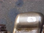
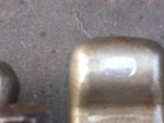
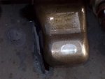
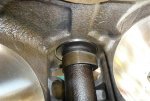
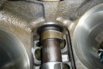
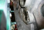
Here are some pics of the wear on the rocker arms. Some of the pads do have a recessed area in the wear spot. Not much but you can definately feel it. The pictures of the valve tips did not turn out well. I'll try again tomorrow when it is light out.
I checked the lifters that are in the motor now and they do have a slight crown to them. The original lifters on the cam I tossed away.
 

Attachments

  • Rocker Arm 008.jpg
    Rocker Arm 008.jpg
    104.4 KB · Views: 390
  • Rocker Arm 007.jpg
    Rocker Arm 007.jpg
    61.8 KB · Views: 385
  • Rocker Arm 002.jpg
    Rocker Arm 002.jpg
    67.3 KB · Views: 387
Wear pattern apears normal and not indicative of an allignment problem. A newly ground valve tip will initialy only cantact on the new sharp outer edges and can chip if the wear spot on the rocker arm is not removed.

Don't think that is causing your valve noise issues. It does make good practice to fix though either buy a set on new boats or have them resurfaced.
 
Thanks for checking out the pictures. Like you said the wear is not that bad. Could probably need a refinishing. Although this still leaves me stumped.
If the valve tip had excessive wear would this not effect how the engine ran? It runs fantastic, nice smooth idle, vacuum gauge does not fluctuate at all, steady at 17". I am getting 16 mpg on the hwy at 65 mph.
When I pulled the previous cam it did not have any obvious wear marks. Although I do not have a way to measure wear on it?
After researching here and on bp I did come across something that made me double think the problem.
The intake manifold that I put on this motor came from my 69 304. I had it baked and blasted and installed on this 70's 304 with emmission air tubes.
Like I said in the first post the rapping noise is loud at start up and diminishes when warm. Can this possibly be a welch plug that is bad? I've read that a bad welch plug will make a noise similar to a bad lifter. As I recall they did not look bad but I should of replaced them as a precaution.
 
The valve tip wear May go hidden for ever and not effect how the engine runs. As soon as the tip beds in to the rocker wear pattern, I would not expect you to ever have an issue except the possibility of a non rotating valve.

A welch plug? Tough to believe but I suppose anything is possible. It would have to be loose enough to pop in and out of its bore but not fall out of leak.

Idk, but as you have seen the manifold vacuum is a constant 17" that would hold a loose plug firmly in its bore, not suck it in and blow it out so it would make a bang.

A couple of items related to my first post to your problem.

1) oil supply to the lifter gallies from the rear cam bearing.
2) incorrect lifter preload.
3) a sticking valve from either to tight of a guide to valve
clearance or lack of oil flow
.

I can fairly confidently eliminate my # 2 and 3 potential causes. 2 because the lifter preload if a given and should not get better and than worse.
3 because you indicate a solid vacuum reading and a sticking valve should give some sort of vacuum fluctuation at a very minimum or like most cases a very rough idle.

That leaves #1. As you know the lifter gallies are fed by a special set of passages from the rear cam bearing. In almost all of the engines I have gone through that were previously rebuilt the rear bearing is installed way to deep. It does a few things that can effect oil flow to the lifters.

This first one I believe is the most important.
1) the cam has a groove in the rear journal that acts as an oil transfer passage, installed to far back and it will be miss aligned restricting oil flow from the bearing to the cam and thus in to the oil cavity behind the cam. The bearing and rear cam journal are basically the same width so when assembled and viewed from the bottom with the oil pan removed it should be clear that the bearing shell is visible protruding about 3/32 (.094) in to the engine and cover the cam journal almost completely. This indicates the bearing is installed correctly. If a major part of the cam journal is visible not being covered by the bearing it is to far aft in the block. Only way to fix it is to yank the engine and reposition the bearing.

2) the aft installation of the cam bearing can block the oil channels that feed the lifter gallies.

3) the oil hole alignment both in clocking and for aft positions can hinder oil flow.

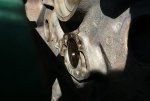
Pictures of one block I recieved in which the cam bearings had been already installed and I moved the rear on about .075 during the photos and moved another .030 later so the cam was completely covered. This was not a severe case but needed to be rectified none the less.

Rear before move
8280d1263052871-cam-valvetrain-issues-p1010234before-large-.jpg


From pan direction before move
8281d1263052871-cam-valvetrain-issues-p1010237before-large-.jpg


Rear after move
8283d1263052871-cam-valvetrain-issues-p1010243after-large-.jpg


From pan direction after move
8282d1263052871-cam-valvetrain-issues-p1010241after-large-.jpg
 

Attachments

  • P1010234before (Large).jpg
    P1010234before (Large).jpg
    51.5 KB · Views: 572
  • P1010237before (Large).jpg
    P1010237before (Large).jpg
    86.4 KB · Views: 573
  • P1010241after (Large).jpg
    P1010241after (Large).jpg
    93.2 KB · Views: 1,485
  • P1010243after (Large).jpg
    P1010243after (Large).jpg
    67 KB · Views: 1,521
Last edited:
What I meant is I have read that there is an exhaust crossover in the intake manifold. A bad welch plug in this area would produce an exhaust leak when cold and diminish as the engine warmed up. Just a thought.
 
what I meant is I have read that there is an exhaust crossover in the intake manifold. A bad welch plug in this area would produce an exhaust leak when cold and diminish as the engine warmed up. Just a thought.

Should see evidence that an exhaust leak exists from black discoloration near the plug or on the valley cover.
 
Good pics Robert!

If ya go to the sonja motor thread, you will see how I installed the rear cam bearing also, and then created an "match" in the bearing shell to eliminate any oil flow restriction.

Simply because of the way the lubrication system is set up on these motors, exact cam bearing positioning is very critical! Probably more so than on any similar engine from other oems, so a machinist has no leeway in bearing installation, it must be done very carefully with complete visual verification all the way! Ya can't just slam 'em in and move on! And even if all oil holes line up, any mis-alignment/overhang must be corrected by alignment drilling through the block or saddles and then hand-finishing with a die grinder.

Also...if the cam bearings are installed backwards (very easy to do), the oil holes will never align! If the bearing installer just pulled just one out of the set and loaded on the tool the wrong direction, then the system is scruud!

I have two boxes of new cam bearings here now that came to me with a bunch of throwaway parts. Both sets had obviously been installed wrong, then discovered and removed. These are one-shot items, ya can't just slam 'em in, then realize they are wrong, remove 'em and use again!

These boat rockers are not worth having "repaired", simply replace with new if there is any doubt as to servicability.

Regarding the rotten welch plug syndrome...those should always be removed before a bake and blast or hot tank. Then new ones installed. Depending upon your exact manifold, not someone else's, you could have none, two or five welch plugs present. Definitely five if the manifold is an egr unit. Only two of the pugs block escape of exhaust gas (the noise referred to in the other thread is an exhaust leak), the other three clock coolant jacket access.

If you suspect an exhaust leak under the intake manifold, stick one end of a piece of vacuum hose in your ear, and slide the other end under the manifold while the motor is running and you will hear an exhaust leak very clearly. And if there is an exhaust leak, that won't show up as a vacuum leak point since the exhaust gas masks it unless you used propane intake manifold gaskets which block the crossover.

You can use the same piece of vacuum tubing and slide down into each pushrod hole while the motor is running and listen to any lifter tick that might be present, works much better than a long-probe stethoscope.
 
I May have found the problem. After reading through this thread and thinking I would hate to pull the motor I figured I would pull the rockers on each head and check things out one last time.
I bolted the rockers back into place tightening from the center and working outward. When I started the engine the noise moved from the #6 cylinder to the #1 cylinder.
I thought this was odd, how could the noise move from one head to the other head?
I figured I would try an experiment. With the motor running I loosened the bolts on the rocker stand on cylinder #1 and the noise went away. I played around with the tightening sequence and found out that the noise would increase or recede by which order the rocker stands were tightened.
I now believe the problem to be screwed up rocker stands. Not knowing the history of this motor. I now have some questions.
What is the height of the rocker stands?
Are the boat style stands the same as the welded stands? Can they be mixed together?
Is there a factory torque sequence? I didn't see one in the service manual.
 
All sv rocker shaft stands are the same height. I measuredusing calipers, a virgin stand and I get 1.313 from the bottom to the lower part of the shaft bore. If they have been rebuilt the bore May be slightly bigger. As long as they are close to the same ground parallel to the bore cl. I would think you are good to go.

As for tightening sequence. I pull them down from the center out and evenly so they all meet the head at close to the same time. Then torque to 16 ft/lb again evenly from the center out.

I don't know why loosening the stand bolts would make a differance unless you have a binding situation.
 
Back
Top