Ain't it amazing how decent electrical ground points can change your life in several ways?? But don't get too complacent, you have just begun your journey through the ground path on these chunks of rust and rot!
As for your trailer harness, are you going to do a simple "four flat" connector as used with trailers that do not incorporate a battery charging circuit, electric brake controller, and an auxiliary circuit???? Or are you going to set up a complete "rv-style" seven pole connector with "flat" terminals inside the connector???
I spent several years in distributing, retailing, and installing towing products for all kinds of motor vehicles/trailers. My advice...set up only a true "flat seven" rv connector on the tow rig from the gitgo. That single connector can be used with many different adapters that are off-the-shelf items nowadays...stuff we always had to fabricate onna individual basis years ago. Even if you do not run the auxiliary circuits for brakes, etc. At this time, the connector will be already set up and ya can go back later and run the additional circuitry as needed.
So I'd obtain a female (vehicle end) rv flat seven connector that is pre-wired with a pigtail out, that is properly color-coded for the industry standards, and you will only actually use four of the conductors, the ground, the left stop/turn, the right stop/turn, and the tail light. The color codes on those connectors is not the same as the code for a plain old "flat four".
The pre-wired connector will have complete instructions included as to the function/color of each terminal, then ya simply connect each wire in turn into the vehicle harness found on the inside/rear of the frame rail. A test light or volt meter can be used to probe for "which" oem wires are need to mate up, though if you have a wiring diagram ya can id this visually.
Do not use "scotchlok" connectors to wire the trailer connector. That is a pisspoor way of doing anything! Simply cut the wire and use crimp connectors to interface the wire runs, then wrap it all neatly in electrical tape and use tiewraps to secure.
If ya wanna go ahead and set the connector up for a brake control and battery charging, then you will need to run two additional wires from the engine bay that are fed from proper circuit breakers...those wires need to be ten gauge, one will carry a fairly significant current load for the brake system, the other will carry a significant current for charging one/two batteries on any so-equipped trailer. I always runs those two new circuits from an auxiliary fuse panel installed in the engine bay for electrical load distribution, only the panel does not use fuses, it uses circuit breakers per the rv code.
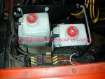
The pic shows a very inexpensive auxiliary fuse panel I use quite often in my work, it's fed from a dual battery setup with an isolator incorporated, and is used for the trailer brakes, charging circuit (two batteries on the trailer), and another circuit I power my vehicle sound system from. So by using the isolator, I have three batteries to pull from for the trailer loads and no possibility of draining my primary "crank" battery.
This link will take ya to one of the best rv/trailer wiring pages on the 'net:
trailer wiring diagrams
And when setting up a tow harness on your rig, do not scrimp on the ground connection!!!! The connector must have a solid/clean ground path to the vehicle frame!
Back in the day, IH offered as an accessory item, the forerunner of the rv-style harness connector we use today. But it was not a "plug and play" type as found today for modern vehicles. It was simply a metallic (not plastic) connector that was pre-wired with a pigtail. And included instructions on which vehicle harness wires to tap into.