

You are using an out of date browser. It may not display this or other websites correctly.
You should upgrade or use an alternative browser.
You should upgrade or use an alternative browser.
Beater's Third Life
- Thread starter Michael Mayben
- Start date
Michael Mayben
IHPA Tech Moderator - Retired & No Longer Online
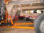
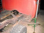
While the bed was hanging and partially supported in the front by the portapower, I just drove the rig out from under the bed. Real slick!
Then it was lowered onto jackstands under each corner that are mounted on roller dollys so I can move the bed around in the shop if need be.
Turns out that the bed was made to the standard frame rail width back in the day of 34". And the IH-produced light duty truck frame rail width is also 34". That's measured "outside" to "outside" of the rails. The Ford frame being a much later model, has "level" frame rails, the light duty IH stuff uses a drop frame. So appropriate risers will be fabbed for the front of the flat bed frame to mate it with the truck frame rails.
Preliminary measurement shows that I need to whack about 24" off the tail if I do the cutaway corners. That will put the gooseneck box ball hole about 12" behind the rear axle tubes. Not the ideal position by any means, but in order to center it, I'd have to cut near-equal amounts off the front and rear of the bed and that involves butchering the headache rack. So that is way more trouble than I'm willing to go to. Goose ball location has to do with trailer weight distribution onto the tow rig axles. Since the IH trucks are extremely "weight-forward" biased anyway and I've added a massive winch bumper, winch, and dual batteries, having the pin box behind the axle on this ride should actually improve overall weight distribution with either a fifth wheel or goose trailer connected. 90% of the time the rig will see only a bumper pull toad with an equalizer set, so the goose ball location is not a deal-breaker.
So the bed tail will be modded quite a bit from the way it appears now, with corners cut away and boxed in. The drop hitch will go away as it's totally useless for our purpose. I don't agree with using a receiver that is integral with a truck bed, so the skirt will be slimmed up a bit and we'll keep the existing receiver as it is.
Underslung boxes May be used in front of the rear wheels if there turns out to be enough room for fuel tank clearance.
I'll go ahead and calc/whack the tail of the bed off next so I can see how it's gonna sit on the rig. But it won't be mounted permanently until the replacement axle is hung and ride height is set...along with laying in the fresh exhaust system.
Attachments
Last edited:
Michael Dimock
IH Parts America Sales Assoc.
Looks like you and me have got the same idea! Except mine is from necessity, as my truck bed could fall off any minute it seems.... starting with a slightly lower quality version of yours, but nothing a trip to cherry city metals and some welding can't fix! You have definitely got a good starting point that is for sure!
My flatbed donor.....
starting with a slightly lower quality version of yours, but nothing a trip to cherry city metals and some welding can't fix! You have definitely got a good starting point that is for sure!My flatbed donor.....
Attachments
Michael Mayben
IHPA Tech Moderator - Retired & No Longer Online
mm, in regards to the hitch receiver, why don't you want it connected to the bed?
If the bed is bolted to the frame how would it differ from bolting the receiver to the frame?
Here's my position on this subject Mark...and some background:
in one of my former lives, I had a business involving wholesale/retail distribution and installation of all forms of towing products that were common in the mid-80's. Handled distribution for reese, draw-tite, sure pull (local operation out of blue mound, tx), and several other lesser-known brands.
I was very fortunate to be able to attend both reese and draw-tite distributor sales and technical training programs on several occasions, and also spend some time in one of the reese manufacturing facilities. This type training was imperative for myself and employees as we performed hitch installs for many oem truck dealerships in the dfw metroplex. If a new truck buyer wanted a tow package installed before delivery, we picked the rig up from the dealership, installed the options, and then returned the rig with all warranty paperwork in the glovebox.
Up to that point, I was just a consumer/user of receiver-type hitch products as I also had a sideline operation going involving load-out/transport of sailboats on a telescoping trailer with articulated bunks.
After participating in the various training programs and learning that bolt-on class II and iii receivers (those were the highest load capacity units available at that time, since then class iv and class v have been added) were actually a "torque-tube" in order to flex to more effectively absorb/distribute shock loads from the toad to the tow rig. And...all the ratings for these products were developed for "bolt-on" applications with no welding to the tow vehicle frame whatsoever!
Once a design is developed for a particular application, it's engineering then must be tested in accordance with:
vesc regulations
In order to be able to carry the common "v5" rating you see permanently stamped on various tow products.
Here's another interesting link regarding this subject which should really hit home for ya:
chapter 204-70 wac: standards for vehicle connecting devices and towing methods
A receiver system integrated into a truck bed or tow body no doubt can far exceed the minimum specifications called for the vesc regs. But those are not "torque-tube" designs either...and...unless the entire package was submitted for testing, will not carry the v5 designations.
And...because of the usually "high" fixed height of the bed-mounted receiver box, that means a seriously-long "drop" ball mount or "stinger" must be used to accommodate the wide range of trailer coupler heights. And long-drop stingers greatly reduce trailer load capacity in relation to the tow rig...seriously reduce the weight ratings!!
Long drop stingers cannot be used with an equalizer system by nature of design (and I personally think are very unsafe to use), and the fact that weight ratings must be decreased so significantly, they would not be usable in a safe manner with any modern "bumper-pull" trailer. Today...most equalizer heads are of the adjustable version which means they can be adapted for use on many tow rigs of varying receiver box height. In the old days, the ball height had to be set after much trial and error...then the equalizer head had to be set at an "angle" and welded to the drawbar by a certified welder. That meant that the typical consumer who had the ability to set this stuff up themselves, still had to have outside assistance to make the final setup. And when the tow rig was traded out or a different rig was used, the equalizer head would not effectively transfer.
Regarding the truck bed I'm using in this project, I'd have no problem using the receiver box for a pintle hitch setup though, as long as the toad with the lunette is properly loaded out. A typical pintle system does not use an equalizer.
That enuff bs and smokeblow for ya??
Michael Mayben
IHPA Tech Moderator - Retired & No Longer Online
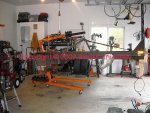
After stealin' the bed off sonja's f350, I had another brain fart.
The Ford has a sway bar system and had at some time in the recent past had some new springs, spring plates, and bump stops installed.
Since the frame rail width between the Ford and the beater 1110 is exactly the same. And the eye-to-eye of the leaf springs is exactly the same (the Ford springs are 2-1/4" wide, the IH springs are 2-1/2"). And the sway bar and lower shock mounts are an integrated assembly retained by a u bolt on each side to the axle housing. And the Ford axle is a d70 with 4" tubes same as my dodge axle. Then that interprets as...I got everything I would ever want/need sittin' right under this Ford!
So after another 30 minutes with the gas axe today, the takeoff stuff is in the shop (except for axle and springs)! Even the top shock mounts for the Ford are riveted to the frame so that was an easy grab. This all means that the sway bar and shock mounts will all bolt right to the IH frame in exactly the same relationship as on the Ford. Just have to bolt the shock mounts to the frame instead of rivet. Even the super-hd shocks appear to be nearly new!
Now my wheels are really spinning...this Ford axle will go right under my ride with virtually no mods other than moving the spring hangers from the Ford over along with the springs. Even the spring mount on the Ford axle tubes are in the correct location to match up with the Ford springs when hung from the IH frame. And the Ford tires currently are users (16" wheels), where the dodge tires are not (16.5") and the Ford drive shaft can be easily cut down and a new slip yoke added to mate with the NP205 output.
So...(I need to sleep on this deal) it would be much less work to simply near bolt-in all the Ford stuff. The diff cover has been off recently (rtv evidence), so no telling what is inside the pumpkin. I need to pull the cover and see..but if it's a 4.56 (best), or a 4.10 (ok), then this May be a no-brainer!
Attachments
Michael Mayben
IHPA Tech Moderator - Retired & No Longer Online
Yesterday, ups dropped of my annual personal re-fueling package from ihon norma! Bakalava is on the bench! This stuff really makes me wanna do stuff, the sugar high is incredible, most especially for a diabetic! Thank you norma!!!!
So, what better time than to take 2ft. Off the flatbed??
I been going 'round and 'round about where ta cut the thing since I really don't want to move the rear axle back. So I split the difference...if I move the axle this will work, if I don't then the proportion should look ok also.
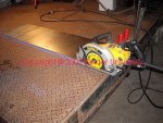
Since this bed is a factory-built item, it's perfectly square and has no damage at all. So it was simple to determine the cut line and then Mark with a chalkstring.
I had a short piece of squarely-sheared 16gauge to use for a saw guide. The framing saw issa cuttin' sumbitch for concrete block and steel with the right blade! This cut took one and a half blades and about 15 minutes of applying just the right amount of speed and feed.
I finished the whack job off with the gas axe and the chunk supported by the cherrypicker.
So, what better time than to take 2ft. Off the flatbed??
I been going 'round and 'round about where ta cut the thing since I really don't want to move the rear axle back. So I split the difference...if I move the axle this will work, if I don't then the proportion should look ok also.
Since this bed is a factory-built item, it's perfectly square and has no damage at all. So it was simple to determine the cut line and then Mark with a chalkstring.
I had a short piece of squarely-sheared 16gauge to use for a saw guide. The framing saw issa cuttin' sumbitch for concrete block and steel with the right blade! This cut took one and a half blades and about 15 minutes of applying just the right amount of speed and feed.
I finished the whack job off with the gas axe and the chunk supported by the cherrypicker.
Attachments
Last edited:
Michael Mayben
IHPA Tech Moderator - Retired & No Longer Online
I'll re-cycle the rear crossmember from the cut-off piece and use it to finish out the rear of the bed frame where the cut was made. The diamond plate will be recycled also into cutaway corners and an apron.
The integrated receiver in the original bed issa massive fabrication, so I'm gonna mod it and mount towards the top of the cutaway on one side, that will serve as a mount point for a vise onna 2" stinger that is removable.
That's about all of the work on this bed for now, I need to actually hang it on the beater frame temporarily and do all the calcs for the cutaway corners, axle position, etc. So now I gotta figgr a way to git it out of the shop bay and out on the parking lot, I'll have to use Todd's camper jacks for that operation!
Attachments
Scoutboy74
Moderator
Nice whack off job! Ain't nobuddy kin whack it better'n you dude! That inlcudes jerry, tho' hez a dam close second.
Michael Mayben
IHPA Tech Moderator - Retired & No Longer Online
Why did I thunk that usin' the term "whack" wuud wake jerry out of hiz latest coma???
Michael Mayben
IHPA Tech Moderator - Retired & No Longer Online
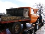
Emerging from another schizophrenic episode involving uncle ed's motor, the dawghauler's on-going weber carb clusterfook, a carter/weber/motorcraft yfa carburetor douche, and parting out the f350, I'm back on the beater rear axle swap.
Rolled the unit into the shop tonite for a differential flush and fill. Ya know me, I pull maintenance the hard way, remove the axle from the frame just to change the lube.
So yore lookin' atta d70 hd geared 4.10 with an open diff. The other axle I have is geared 4.56 which is what I really want, but I'm not gonna go to the trouble of swappin' gears until I can do a Powr-Lok or equivalent later on.
The spring sets are newer stanley replacements in a 4800lb. Rate each. The overloads add 2300lb. Each side.
I'm planning to remove the overloads now, then I'll add a set of two inch/6* riser blocks between the spring and perch on each side to point the pinion angle a bit more favorably since this is a short wheelbase ride. The oem risers on the takeoff d44 are also two inch flats. Overall, if my calcs are close, this will give an effective lift of about three inches over stock, which is right what I had planned for in the beginning, except now the pinion angle will be optimized also!
I'm also going to incorporate the Ford parking brake cable balance set since on the Ford the cable runs down the driver side instead of right in the middle of the frame. That allows much more clearance for tucking up the exhaust pipes on the passenger side.
Attachments
Michael Mayben
IHPA Tech Moderator - Retired & No Longer Online
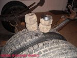
This is a set of timbren "airless" overloads. These perform the same function as the overload leaf springs but are far less aggressive. Same concept as air bags only these units are hollow.
These are rated at 6,000lbs. The pair, and the action is progressive with compression.
These units were mounted to the donor rig in addition to the conventional overload leaf set. So for now, I'm gonna remove the leaf overloads and go with the timbrens only and see how that works out. If they don't, then the next step would be the true airbag install.
The rear section of the Ford two-piece driveline is about a foot too long so it's a perfect candidate for a cut-to-fit by the local driveline shop where I'll have a new slip yoke stuck on the front to match up with the oem NP205 rear output.
I've now decided to move this axle back from the original hanger positions by 6>8". So the wheelbase is gonna be a kinda bastard, but who cares?? The 1110 frame already has two sets of punchouts for two different spring sets, one for a 2x4 setup, the other for the 4x4 spring position. Moving the axle rearward will put the gooseneck box right where it needs to be over the axle for use with either a neck-over trailer or a fifth wheel, and will allow a full 90* jacknife of a typical fifth wheel rv with no cab corner interference, negating the need for a slider hitch.
Even the rear brake flex hose mount is in exactly the same position as the original IH bracket for the d44.
Attachments
The only downside of this project I can see is the rear brakes Ford used. Not one of their better ideas imho.
When they work they work okay but when it comes time to reline, reinstalling the brakes springs is not a fun task.
All I can say is what a dumb way to mount brake springs.
When they work they work okay but when it comes time to reline, reinstalling the brakes springs is not a fun task.
All I can say is what a dumb way to mount brake springs.
Michael Mayben
IHPA Tech Moderator - Retired & No Longer Online
Here's the completed d70 axle package ready to install.
The overloads have been removed as they are not needed now. In their place went a set of trailmaster 2" cast iron lift blocks with a 6* wedge to help out the pinion angle.
The axle in this config has a gross rating of 8600lbs.
The blitz to get this package installed began Friday afternoon. This rig must be on the road (though not fully completed) on Monday morning. It's gonna go down the road on the front axle only, once the ride height is finalized, the replacement rear drive shaft will be made up.
Attachments
Michael Mayben
IHPA Tech Moderator - Retired & No Longer Online
These oldskool camper jacks of toddjo's are dam useful around here!
Lifting the rig here completely clears out the area to the rear so that the axles can be rolled around and positioned as needed.
And, the winches allow minute up and down positioning for axle alignment, assisted by line-up drifts, pry bars and a big hamdammer!
While it was still outside the shop I torched all the spring hanger rivets except one on each hanger. Same for other superfluous hardware.
Attachments
Michael Mayben
IHPA Tech Moderator - Retired & No Longer Online
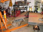
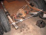
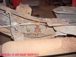
Here's the glider after all the oem crap was out of the way.
Note the original front spring hanger position. The second mount point 4" to the rear of the point where the 4x4 spring was mounted is the 2x4 axle/spring mount position. Neither of those points will be used with the Ford spring hangers.
Note the original front spring hanger position. The second mount point 4" to the rear of the point where the 4x4 spring was mounted is the 2x4 axle/spring mount position. Neither of those points will be used with the Ford spring hangers.
Attachments
Michael Mayben
IHPA Tech Moderator - Retired & No Longer Online
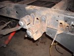
This is a shot of one of the rear spring hangers that has the oem swing shackle. It has two mount points on the side of the frame rail, with a "tab" riveted to the bottom flange.
The gas axe makes short work of the rivet heads, the tails will be punched through during the final frame clean-up and prep for some rattlecan paint.
The gas axe makes short work of the rivet heads, the tails will be punched through during the final frame clean-up and prep for some rattlecan paint.
Attachments
Michael Mayben
IHPA Tech Moderator - Retired & No Longer Online
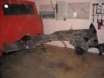
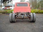
Here's a preview of the completed install. Each hanger has two bolts installed so I could roll it out of the shop and move the oem axle out of the way and onto the parking lot.
There is much detail work left to perform, drilling all the holes by hand with a dewalt bullet bit eats my lunch, a total of 26 holes have to be drilled, most all are 1/2".
There is much detail work left to perform, drilling all the holes by hand with a dewalt bullet bit eats my lunch, a total of 26 holes have to be drilled, most all are 1/2".
Attachments
Michael Mayben
IHPA Tech Moderator - Retired & No Longer Online
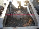
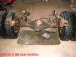
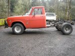
And a profile.
The axle has been moved 11" to the rear of the oem axle centerline. That will put the gooseneck pin box in the bed floor right where it needs to be over the rear axle.
That also sets the rear spring hangers right in the midst of the reinforced rear frame sections that ihon Darren did for me a few months back!
Just as I started to torch off the oem overload bumpers on the frame, I ran out of o2 for the gas axe! No way to get any gas around here on Saturday afternoon!
But...the Ford front spring hangers fit perfectly over the front overload bumpers on each side, that is exactly the position I had intended to use!
The nose-down attitude is accentuated since the front wheels are sitting in a depression in the parking lot. And it's certainly not gonna stay that way! I have a couplea plans for the front axle sitch now, it's all gonna be dependent upon budget and what alternative axle I can come up with. Prolly for the short term, the Ford overload spring paks will be incorporated into the oem front springs, looks at this point like the total lift over the stocker is gonna come in right at 4". The tires on the d44 are exactly 1/2" shorter than the 16" rubbers on the Ford wheels.
The completed bed with toolboxes loaded out should come in at about 1300lbs., so that will squat the azzend about 1.5".
Attachments
Scoutboy74
Moderator
Lookin' gud! Beaterz gotta real purdy bee-hind now
Michael Mayben
IHPA Tech Moderator - Retired & No Longer Online
lookin' gud! Beaterz gotta real purdy bee-hind now
And her azzend goes real straight down tha road too!
Bitch izza driver again, but many details yet to tend to. Ride ain't quite as hard as I figgrd, the truck box mounted helps, and the bed will make it just right.
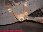
Here's the deetale on the Ford front spring hangers, ya can see they laid right on top of the oem front overload bumper.
Two different size bolts were used, that way I could align the hangers using oversize holes, then go back and re-drill for the final install. This mounting point on the frame kickup is far stronger than the former location of the oem hanger.
Attachments
Michael Mayben
IHPA Tech Moderator - Retired & No Longer Online
Brakes are major! The bigazz Ford brakes, combined with the oem 3" lockheeds on the front provide major stoppage now (never had any issues before however), no way I'd ever use discs on this ride!
The only change in the brake system involved splicing in 12" of 3/16" pigtail. The Ford flex hose is the perfect length when re-routed, though I will replace it with new as soon as I can score one.
Those CPT brake hose mount tabs are just the ticket for doing stuff like this, just put 'em where ya need 'em!
All this bogus wiring schnizz will disappear real soon, the rear chassis wiring harness will be run fresh from the cab corner back to allow wire runs for clearance lights on the bed and all new trailer wiring. A pair of floods will be mounted on the headache rack to illuminate the rear for lighting for hitching, and waterproof 12vdc power connectors will be installed at strategic locations on the bed.
Once all the wiring is prepped and protected, then the entire harness will be secured to the frame.
The only thing left at this point is to fab two tabs for mounting the sway bar links. The Ford links ended up being about 2" too short since I used the 2" lift blocks.
Attachments
Michael Mayben
IHPA Tech Moderator - Retired & No Longer Online
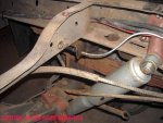
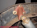
Detail of the Ford shock mounts that were torched off the f350, really nice pieces that fit perfectly inside the frame "c" exactly like the Ford install!
These would make great fab pieces, just like those f-150 front shock towers we peddle here at ihon!
I can already tell from the test drive that the shocks mounted like this are a vast improvement in axle control over the oem IH whacko mount setup! With the bed installed and a trailer in tow, this thing is gonna handle perfectly!
Attachments
Michael Mayben
IHPA Tech Moderator - Retired & No Longer Online
Don't have time to complete the parking brake actuator tonite, but the Ford cable stop is now mounted inside the frame "c". On the f-350 it mounted on the outside of the frame rail.
So the oem "center pivot" parking brake anchor gets tossed. The cable itself will come straight back inside the frame rail like it was supposed to be that way, that gets rid of the oem cable equalizer which in turns really opens up the area for exhaust pipe routing.
All it's gonna take is about 14" of cable extension to connect to the Ford equalizer/adjuster. It's sooooo nice to have this whole deal turn out to be a bolt-on swap with really no fabrication involved! Just a buncha holes to drill.
Next up along with the wiring, is a complete fresh exhaust system. Now that the axle is mounted, I can see exactly where I want the muffler, and the tail pipes will come out in front of the rear wheels.
Looks like now the Ford drive shaft will end up working. I've got a 1350 yoke for the np 205 output shaft that will be mated to a new slip yoke to be installed on the cut-down Ford driveshaft.
Attachments
Last edited:
Monte Lauer
Active member
Looks real good, but I still would of liked to have seen the old box with a dually axle underneath it. 