I just bought my first Scout and it had some leaks so I took it to my mechanic and he is having an issue finding a vacuum diagram for my vehicle. It is a 304 and has no egr valve. The only diagrams we can find have the egr valve. Im not really sure on what the exact issue is. And as I am not knowlegable on the engine I was hoping someone could help me with this so I could relay the information to my mechanic.


You are using an out of date browser. It may not display this or other websites correctly.
You should upgrade or use an alternative browser.
You should upgrade or use an alternative browser.
1970 Scout 800a 4wd w/304
- Thread starter neildsim
- Start date
Michael Mayben
IHPA Tech Moderator - Retired & No Longer Online
I don't have a copy of the Scout 800a and 800B service manuals to reference for a vacuum schematic.
This scan is a "generic" diagram for the earliest Scout II equipped with the Holley 2210 carburetor. Your s800 should have a Holley 2300 carb as oem and the hookup is slightly different.
This diagram also if for the a.I.r. (air injection) system which May or May not be present on your application. If you do not have a functional egr system, then eliminate those control circuits.
If you post some well-focused, semi-long shots of the top of your engine looking straight down, we can provide more definitive information for you, there are many variations of how these engine/chassis May have been produced to meet various 49 state and California emissions specs.
The essential vacuum connections are:
1) pcv.
2) power brake booster (if equipped).
3) "ported" vacuum connection to the distributor vacuum canister directly from the carburetor (0"hg>3"hg at base idle).
Everything else is emissions related.
Attachments
Last edited:
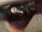
I dont know if this helps but he says the pressure is pushing oil out of the dipstick. There are two valves one on each of the valve covers and they are closing when the pressure goes up. One of the mechanics said he thinks that distributor vacuum canister May not be working because its not changing his timing? Im sorry if im vague but I dont know that much about engines.
Attachments
Last edited:
Michael Mayben
IHPA Tech Moderator - Retired & No Longer Online
The story is always in the pictures when dealing with this old crap that others before you have spent many hours in scruuin' up!
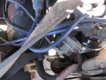
The rig uses only two vacuum fittings/paths. Disregard that entire vacuum schematic I previously posted, that is of no help regarding this vehicle.
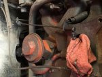
One of the parts installed in one of the valve covers is a "cleanable" pcv valve manufactured by ac sparkplug and is not a throwaway. Those are to be taken apart and cleaned/serviced/tested.
The other fitting should be a "flame arrestor", nothing more than a nipple screwed into a baffled area of the valve cover. It's filled with wire mesh like a brillo pad and must also be cleaned by soaking in solvent. That allows clean air routed from the air cleaner to enter the engine when the pcv valve is open to vacuum which pulls blowby gases out of the engine and then burns the vapors through the combustion process.
I've posted many times in these forums regarding the various ways that pcv was plumbed on different IH vehicles, there is no one "right" way to do this, ihc used several plumbing schemes over the years. I've also posted the process for servicing the cleanable pcv valve, couldn't be more simple.
Do a search here using keyword "pcv" and you will find much information. The engine must be able to "breathe" through the pcv system, otherwise the crankcase pressurizes as you have seen and oil will be forced out of every gasket and seal.
The other vacuum path is from the fitting on the side of your Holley 2300 carburetor which goes directly to the vacuum canister on the Holley distributor. That is the "ported" vacuum port for that carburetor as I previously described.
To test the vacuum can, have your mechanic hook it to a mityvac hand-held vacuum pump and test. It must hold vacuum indefinitely, otherwise it's nothing more than a vacuum leak. Those items are not available from any source as new, we've been looking for over 10 years. But we do have on the shelf reconditioned ones that are indistinguishable from new.
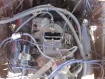
That carburetor is a reman from tomco. Tomco went tits-up nearly 10 years ago though sometimes ya still see their parts laying on the shelf. Those carburetors are infinitely rebuildable, I do 'em every day for our customers, one of our top selling items. My x-ray vision tells me that carb is in bad shape internally!
The rig uses only two vacuum fittings/paths. Disregard that entire vacuum schematic I previously posted, that is of no help regarding this vehicle.
One of the parts installed in one of the valve covers is a "cleanable" pcv valve manufactured by ac sparkplug and is not a throwaway. Those are to be taken apart and cleaned/serviced/tested.
The other fitting should be a "flame arrestor", nothing more than a nipple screwed into a baffled area of the valve cover. It's filled with wire mesh like a brillo pad and must also be cleaned by soaking in solvent. That allows clean air routed from the air cleaner to enter the engine when the pcv valve is open to vacuum which pulls blowby gases out of the engine and then burns the vapors through the combustion process.
I've posted many times in these forums regarding the various ways that pcv was plumbed on different IH vehicles, there is no one "right" way to do this, ihc used several plumbing schemes over the years. I've also posted the process for servicing the cleanable pcv valve, couldn't be more simple.
Do a search here using keyword "pcv" and you will find much information. The engine must be able to "breathe" through the pcv system, otherwise the crankcase pressurizes as you have seen and oil will be forced out of every gasket and seal.
The other vacuum path is from the fitting on the side of your Holley 2300 carburetor which goes directly to the vacuum canister on the Holley distributor. That is the "ported" vacuum port for that carburetor as I previously described.
To test the vacuum can, have your mechanic hook it to a mityvac hand-held vacuum pump and test. It must hold vacuum indefinitely, otherwise it's nothing more than a vacuum leak. Those items are not available from any source as new, we've been looking for over 10 years. But we do have on the shelf reconditioned ones that are indistinguishable from new.
That carburetor is a reman from tomco. Tomco went tits-up nearly 10 years ago though sometimes ya still see their parts laying on the shelf. Those carburetors are infinitely rebuildable, I do 'em every day for our customers, one of our top selling items. My x-ray vision tells me that carb is in bad shape internally!
Last edited:
It is hard to tell from your pictures...
But, it appears that you have two "cleanable" pcv valves in the valve covers.
The rubber hose from the "rear" of the manifold blocks the "view" the "valve" on the pass side.
Where does the rubber hose from the "rear" of the manifold "run" / connect(?) to?
One "problem" is that it appears to me that the valve covers are on the "wrong" side of the engine -- the valve cover with the oil fill should be on the pass side of the engine.
As mm stated, one valve cover should have a pcv valve and the other should have a "flame arrestor" (described by mm above - probably find a picture of one in the ihon store).
Not sure (but mm can confirm), the pcv valve should be connected to the fitting on the rear of the intake manifold -- where the rubber hose currently leads over the pass side valve cover and "down" to (?)...
The flame arrestor should have a hose going into the base of the air cleaner (assuming the air cleaner is stock) above the air horn of the carb.
As mm stated, there are a few variations based on fed smog / CA smog / etc...
Hth
Michael Mayben
IHPA Tech Moderator - Retired & No Longer Online
Really doesn't matter which side the valve cover with an oil fill is mounted to. That is dependent upon which body/chassis these engines are installed in. Some variations of these engines (most especially the 266 and 304) had no oil fill in the valve cover, the filler tube is mounted to the timing cover.
All that matters is that the pcv valve is plumbed correctly to a vacuum source...and that it's flow direction is observed. It can mount in a valve cover, in a stamped boss on the rear of the valley cover, can be screwed into a "vacuum tree" at the rear of the intake manifold plenum, etc. There is no one "right" way,...though for a purist there is a particular mounting used by each model year and platform for vehicles manufactured after 1961ish. If the valley cover does not have a boss for mounting a pcv (either the screw-in version or the push-in version, then the cover has no baffle and the pcv valves should never be mounted in an un-baffled location.
The "fresh air intake" plumbing on a closed pcv system such as that Scout 800 was equipped with always leads to the clean side of the air filter and draws through a flame arrestor. The earlier version of an "open" pcv system lead to a fitting on the oil filler tube on engines with a filler neck mounted to the timing cover/front.
If...a valve cover has the 3/8" npt boss installed, that means there is a baffle spot-welded to the inside of the valve cover to protect the boss inlet from direct oil throw-off from the valve train.
Need shots posted of each valve cover as it is now to see if the engine has the correct pcv and flame arrestor or a combination of wrong parts that prevents proper pcv operation which is the root of the issue here.
Scoutboy74
Moderator
The object in the rear of the engine is an egr valve...exhaust gas recirculation. It is an emissions control device. The other item is either a high or low temp vacuum control switch. It reacts to coolant temperature. Its possible that these two items are meant to be interconnected on your engine. You've piggy-backed a moldy oldy thread about a 1970 800a with 304. Is that what you have?
Scoutboy74
Moderator
For a '68 Scout, the only vacuum line or lines that need to be connected is the ported source to your distributor vacuum advance, a larger diameter hose to your vacuum assist brake booster...if so equipped...probably not in your case, and a line to your vacuum assist wipers, unless they happen to be electric. That emissions stuff offers no performance benefit. IHPA even offers an egr block off plate that you can install in place of the valve if desired. You don't need to worry about capping the hose ports on that switch or valve. There's no vacuum leak from those locations.
FDChappie
Well-known member
I don't think IH engines were equipped with egr valves until '74 so as scoutboy said just the vac advance to the dizzy will do. You might want to swap to a non-egr intake manifold just in case the smog police take a peak under the hood. There was a time in CA where the vehicle was smogged to the year of the engine if it was swapped. I don't know exactly how those vehicles were grandfathered in.
Scoutboy74
Moderator
I don't have access to mt123 which is the IH parts bible for the Scout 800 a & b models. I've scanned the engine section of mt113 which pertains to the s80 and early 800 models prior to the a/b suffix, as well as that of mt124 which pertains to IH fullsize from '69-'71. Nowhere in those could I find any mention or illustration of an egr valve. I too am skeptical of an egr valve setup being original to a '68 Scout, but I can't say with certainty because I just don't know when that device first appeared in the Scout platform. I wonder though as it pertains to certification, isn't a '68 exempt from that pretty much everywhere, making it a moot concern?