Ol' Yellar

Status
Not open for further replies.
This is the fuel tank mount coated in sanding dust.

Mikee is gonna sterilize the tank on Sunday (he doesn't know that yet) and it will go to American spirit on Monday for installation. The tank has to be mounted before the bed goes on the final time, otherwise the fasteners can't be accessed.

Also on Monday, the radiator goes to eugene radiator for a freshening, it doesn't leak currently, but it does need to be cleaned out by a pro!
 

Attachments

  • Fuel Tank Mount.jpg
    Fuel Tank Mount.jpg
    68.7 KB · Views: 300
Mendomikee is on his way here now to jack me up about ed, so I had to do sumthin' to look like progress has been made before he got here!

The gizzwheel took care of the broken manifold studs. That composite gasket is literally welded to the flange and much more handwork is gonna be required to prepare the surface for the new gasket.

See that exhaust heat riser valve? It's frozen in the closed position!! All exhaust gas must go up around the intake manifold and then back down and out through two small holes!!! About the same effect as crammin' a dam tater up the exhaust pipe, bitch can't breathe worth shit!! Don't know yet what I'm gonna do, but it ain't goin' back together like that! If I can't free it up with some very careful persuasion, then it's gonna be removed completely, I can't risk cracking this irreplaceable rotten manifold!
 

Attachments

  • Exhaust Manifold Stud Repair 001.jpg
    Exhaust Manifold Stud Repair 001.jpg
    106.2 KB · Views: 276
The manifold then got jigged in the drill press and the two broken studs drilled out. The holes are drilled completely through the casting so that was simple.
 

Attachments

  • Exhaust Manifold Stud Repair 004.jpg
    Exhaust Manifold Stud Repair 004.jpg
    79.2 KB · Views: 274
While the manifold is still in position on the cross-slide vise, the tap is then started into the prepped hole using slight pressure and turning the chuck by hand. Both holes were started.

Then the manifold went on the bench and the tapping operation was completed by hand.

The gasket set is on it's way in along with the bearing sets, once the stuff shows up, I'll mount the two manifolds together "loosely" and prep for paint. Once the manifold set is mounted to the block snug to seat the manifold gasket, then the nuts on the four studs will be seated to draw everything into alignment with out stressing any of the cast iron.
 

Attachments

  • Exhaust Manifold Stud Repair 006.jpg
    Exhaust Manifold Stud Repair 006.jpg
    77.8 KB · Views: 261
The sparkmaker was a real pile! Juryrig deluxe!

One of the anchors for and advance spring was homebrew and that was hanging up the mechanical advance so it was inop. In addition, one of the advance springs was a total pos and was also grinding on the breaker plate as the shaft spun.

So all that damage was corrected, the bent breaker plate was straightened and the damage ground away.

Then the counterweight assembly was re-installed and lubed with anti-seize.
 

Attachments

  • C-1 Counterweights.jpg
    C-1 Counterweights.jpg
    60.7 KB · Views: 324
Digging deep in my pile of old motorcycle ignition system gadgets and spares, I found a set of advance springs which came out of a honda c-110 (remember the50cc honda super cub circa 1963??).

Cut two turns off each spring and they now are a perfect fit! Ya think this delco remy distributor knows it's got antique japanese motorscooter schnizz inside?

Don't ask...don't tell, I seriously doubt ed will ever see pebble beach.
 

Attachments

  • Advance springs.jpg
    Advance springs.jpg
    60.2 KB · Views: 326
Of course the breaker points were fooked purdy good also, the ignition switch had obviously been left on at some point and the points showed signs of excess heat.

The ground point plate was also bent all ta shit for some reason. But now everything is fixed and in proper order.

I made new insulators for the point connector out of some nylon bushings I use for Holley distributor rebuilds. All of the original insulating materials were turned to particulate, so I made a new one out of cork/rubber sheet material. The points cleaned up nicely, but today I located a supplier for new breaker points for the delco distributors so if need be, that won't be a deal killer.

Keep in mind this rig has been half-assed converted to 12vdc and the wrong ignition coil used with no ballast resistor. All that will be corrected when the fresh electrical system is laid in.

The paint work on the distributor is "chassis black", same as what the rest of the undercarriage is done in.
 

Attachments

  • Electrical Complete.jpg
    Electrical Complete.jpg
    55.8 KB · Views: 321
Here's the sparker ready to drop into the block.

Some of the pieces for mounting the vacuum advance were missing, but I was able to work around that with new hardware.

The vacuum advance unit actually rotates the entire distributor body through it's range of motion, approximately 5*. I was able to locate two iridite-plated nuts to mount the reconditioned vacuum advance with so the hardware matches. These are the advance units we have reconditioned for ihon and are indistinguishable from new...and even the tiny delco remy logo stamped into this one was preserved and is legible!

The distributor cap likewise appears original, the delco logo is present on it also and it's in excellent condition after some careful clean-up, same for the rotor.
 

Attachments

  • Ready To Fire.jpg
    Ready To Fire.jpg
    73.6 KB · Views: 335
Hmmm, those springs do not look like they have enough "tension", but I assume you ran the dist on your machine.

If you want to try some nos corvair dist springs (delco 6 cyl), I can send you a pair. We can "discuss" which "corvair engine" is a "good fit".
 
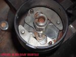
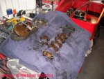
hmmm, those springs do not look like they have enough "tension", but I assume you ran the dist on your machine.

If you want to try some nos corvair dist springs (delco 6 cyl), I can send you a pair. We can "discuss" which "corvair engine" is a "good fit".

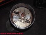
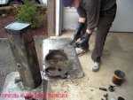
The distributor springs are supposed to be "slack" when the advance counterweights are static. Lots of slop. I have all kinds of delco, Holley/motorcraft, and other distributor advance springs to chose from. The delco "curve tuning" kits are readily available here locally, I keep 'em in stock to use the pieces for all kinds of stuff, some of the delco springs I use in Holley distributors currently. The particular diameter springs I chose allow sufficient clearance under the breaker plate to prevent interference when in rotation. That is what was wrong with the unit when I found it...someone had bent the shit out of the breaker plate trying to make clearance, the springs that were in it were too large in od and were not oem!

So...the mechanical advance had not been operational in ages no doubt, and the distributor was locked down since the vacuum advance was inop also. In order to allow the engine to crank without kicking back and breaking the starter drive, the timing was greatly retarded and had no form of operational advance system.

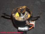
Keep in mind, while these units are a very early form of delco remy sparker, they have little in common with the delco distributors supplied post-wwii, particularly in their very compact size.

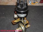
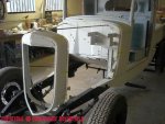
The externally-rotated advance system was used on many IH six banger motors up through the late 50's though. Most engines/vehicles from the teens through the late 30's used a mechanical spark advance controlled from a lever mounted on the steering column...retard the spark to start the motor, then advance the spark to run, the advance lever was positioned based upon the quality (octane rating) of the particular fuel being burned. For burning kerosene or "drip gas", ya could not advance the spark control at all! The willys-overland/ihc motor was somewhat unique for the times in that it had a vacuum advance system incorporated instead of a manual control lever.

I don't have a distributor machine to test run these sparkers, I do it with the engine running and using a tach and dial-back timing light to test the advance curve.
 
Yeah, I know the distributor is smaller, but the distance between the spring posts looked "close". But, I have not been into the "guts" (below the point plate) of my corvair distributors in many years.

The reason I asked is that the springs in the corvair dist are under slight "tension" -- I even bought the tool to put in / remove the dist springs.

I would think that "loose" springs would have a chance to come off when running. I had one come off in my corvair dist (incorrect installation?) and the weight carved a groove in the inside of the distributor housing.

Looking for springs, I came across an article on corvair distributors -- someone had compiled (70's) the "specs" (cam / plate / springs / vacuum advance) for 30 corvair distributors (30 different GM part numbers for the distributors).

Enjoying the documentation of the project.
 
Mikee actually did shit on his own rig last weekend! He was assigned that part that involves cleaning up some really nastee shit!

Unfortunately, the fuel tank is in somewhat worse condition than we had previously determined, once we had it clean. Lots of solder repairs over the years, the sender/pickup was totally botched with a rotten/sunken float. Someone had actually cut it open at some point, then closed it up and stitched the patch with solder. The cast iron filler neck had also been butched and soldered which has broken loose again allowing fuel leakage when being filled. And the boss for the sender has also cracked out.

The tank is at the stripper's now (the radiatordude doesn't deal with tank clean-out), then tracy will iron out the sheetmetal damage. Once it's straightened, it goes to radiatordude for a total re-solder. I have the parts on the bench to fabricate a replacement sender, more on that later.
 

Attachments

  • C-1 Cleanup 003.jpg
    C-1 Cleanup 003.jpg
    98.8 KB · Views: 300
Mikee got started on engine component cleanup and removed all the bearing inserts so he could have some trinkets for posterity.

Turns out that nearly all the upper rod bearings had been shimmed with shim stock, when that was done (who knows when??), all the oil holes in the bearing shells were blocked!!!

I picked up the crankshaft from the machine shop last week, the replacement main and rod bearings arrived here yesterday, more on that later also. The gasket set is still a few days away from delivery.
 

Attachments

  • C-1 Cleanup 004.jpg
    C-1 Cleanup 004.jpg
    103.8 KB · Views: 309
We spent most of Monday with tracy and kenny at American spirit going over the final prep for painting and all the details that remain to be done as far as completing the rolling chassis and body.

The radiator shell, skirts, body, and bed have been temporarily mounted in position for blocking. Those pieces will be one color and must be blocked in a continuous plane before painting. Then the parts will be lifted off again and set into position and hung in the paint booth for total paint coverage inside/outside/underneath.

The fenders and running boards, along with headlamp buckets will be painted in a separate phase since their color will be different.

Tracy has made replacement body insulators and fabricated the fabric anti-squeak strips that will be trimmed to fit during final body install.
 

Attachments

  • Body for Blocking.jpg
    Body for Blocking.jpg
    75.8 KB · Views: 305
Crappy shot but ya can see the assend in this view.

One of the doors has been replaced in toto in the past!

The door hinges are very similar in design/execution to Scout 80/800 hinges! But one of the hinges on the driver door is actually made for the passenger side! Slight difference but noticeable. We finally determined that it had come out of the factory this way so it will remain as one of those personal touches from 1935.

The bed will be done in color-matched bedliner material, I'm sourcing new tailgate chain and hooks now, one of the hooks was made from a blacksmithed bolt and the chains have been patched too many times.
 

Attachments

  • Bed Prep.jpg
    Bed Prep.jpg
    57.3 KB · Views: 292
Lottsa patch and prep work was done on the floorboards. But overall they were in excellent condition.

In the past, the access panel in the floor for the oem battery location had been jury-rigged. So tracy fabbed a correct replacement that can be removed. My plan is to mount the hydraulic brake master cylinder right below that removable cover to allow access to check the fluid level, that way I don't have to use the remote-mount reservoirs I had originally planned for.

The floorboards, along with the entire inside of the cab will be painted in body color as was the original. There were no interior trim panels used on this rig originally, only a rudimentary headliner which will have to be fabbed using the original stuff as a template. The doors do have steel interior cover panels.
 

Attachments

  • Floor Prep.jpg
    Floor Prep.jpg
    72.7 KB · Views: 313
This is the original data plate that was attached to the passenger side running board skirt.

There is a similar plate attached to the wooden window support frame inside the cab that identifies the body builder.
 

Attachments

  • Data Plate.jpg
    Data Plate.jpg
    78.5 KB · Views: 300
Status
Not open for further replies.
Back
Top