T407/TF 727 DIY Reseal

Michael Mayben

IHPA Tech Moderator - Retired & No Longer Online
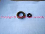
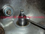
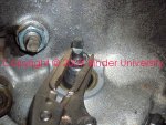
As a companion to the "band adjustment" thread for the tf 727 transmission and it's variations, let's take a look at another diy service process that many folks have asked about...stopping all the fluid leaks!

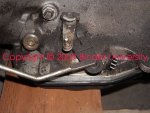
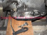
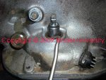
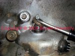
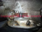
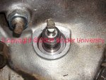
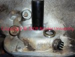
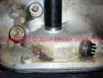
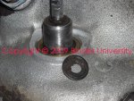
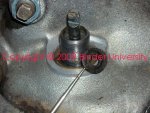
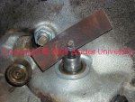
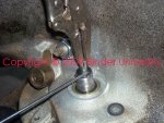
First we'll look at replacing the shifter shaft/throttle pressure seals, then move onto the front pump seal and bushing replacement (requires tranny removal), and then the output shaft seal system both for married and divorced transfer case installs. Any 2x4 IH rig equipped with a 727 uses the same output shaft/housing (aka tailshaft) as used in 4x4 pickall apps. Only the Scout II 727 is set up with a married transfer case.

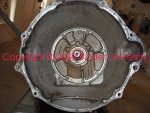
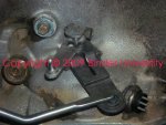
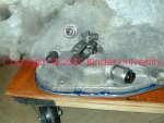
The trans we'll be looking at here in the beginning is a tf 727 from a '91 dodge cummins rig with a married 205 transfer case...aka the "first gen" cummins setup for dodge. Based upon my research, it looks like the "second gen" cummins-powered dodge rigs used the 518 version of the 727, which then became the 46rh. The reseal process for all those trannys is basically the same.

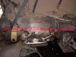
This is the powertrain that is currently being installed in major's torkasaurus project:

http://www.forums.IHPartsAmerica.com/I-h-s-t-o/792-project-torkasaurus.html
 

Attachments

  • W250 Cummins 727 1.jpg
    W250 Cummins 727 1.jpg
    104.2 KB · Views: 9,477
Here's a shot looking into the bell housing area with the torque converter removed. The input shaft seal can be easily seen in this shot, that is an oem-type "silicone" seal.

Directly above the input shaft at the top of the front pump housing you see a small circular "hole". That is the only vent for these transmissions.. In many cases if the transmission is overfilled and then allowed to overheat, oil will pump from that location and run down the inside of the bell housing. Many times that is misdiagnosed as a "seal leak" when in actuality it's really only a service issue that does not call for removing the transmission from the vehicle.

Earlier versions of the 727 will have a sheetmetal "baffle" located over the vent, it's retained by two of the front pump bolts. That vent location is the primary point of entry of water into the transmission in a high water crossing.

There is a large od "o" ring on the peripheral of the cast iron pump housing that seals it to the case, along with a circular gasket between the pump body and the case which serves to seal the internal hydraulic passages. I've never found a tranny that was leaking from either of those locations.

The capscrews which retain the pump body to the case must have the "special" sealing washers installed under the washerheads. Those seal washers are rubber-coated thin steel and prevent oil migration through the threads and out under washerhead.

Later in this thread we are gonna replace that seal and the bushing in the front pump also. If that bushing is worn (very common), it allows the torque converter to slop around on the assembly and prevents the seal from...sealing. Standard practice on these units is to always replace the bushing when replacing the seal.
 

Attachments

  • W250 Cummins Trans Pump Seal.jpg
    W250 Cummins Trans Pump Seal.jpg
    113.4 KB · Views: 8,418
Here's a shot of the shift lever/throttle pressure control interface. Very common tranny fluid leak point on high milage units.

There are two seals used at that point, one is a metal-encased seal for the shift shaft to which the shift lever attaches on the outside, and the "rooster comb" attaches on the inside. The rooster comb actuates the nss system/backup lights and serves as a detent component for transmission shift valve positioning.

The throttle pressure control lever (kickdown lever) has a much smaller seal which seats inside the shift shaft and is retained by a shim washer and "e" clip.

Having the tranny out of the rig makes this job appear easy. Doing it with the tranny installed can be a bitch!

Whether ya are dealing with a pickall or a sii, ya gotta remove the tranny tunnel inside the cab to access this point. I have done a few pickalls without doing that and I'll never do that again! I also did one sii and it was even worse, there is no way to properly clean the seal seat and shaft if ya can' access it from above.

Take the time to remove the hump...even with the hump gone, it's still difficult to maneuver down into the area where we're working!
 

Attachments

  • Shift and throttle pressure control leak.jpg
    Shift and throttle pressure control leak.jpg
    129.3 KB · Views: 10,308
Before going any further, clean the area around the levers really well! We don't want any particulate getting down into the shift shaft area while working here, not a single particle of mung!

Here ya see the pinch bolts for the throttle pressure lever loosened, the levers pull straight up and can only be re-installed at a single position. Set 'em aside for sterilizing.
 

Attachments

  • Shift lever removed.jpg
    Shift lever removed.jpg
    151.4 KB · Views: 8,853
Here ya see the two seals we're dealing with.

The larger item is a conventional single lip seal with a steel case.

The smaller seal is for the throttle pressure control shaft and is a single lip seal also, but closely resembles a grommet and has no case...it's flexible.

Identify the lip on each seal...the lip must point down towards the fluid reservoir when installed!
 

Attachments

  • Replacement seals.jpg
    Replacement seals.jpg
    52.4 KB · Views: 7,220
Were gonna r&r the shifter shaft seal first. That way we don't have a risk of allowing any trash to get down inside the throttle pressure shaft.

I use a cotter pin extractor tool for doing this. I've ground the "outside" of the tip flat, removing just a small amount of material and and being careful to not overheat the tip when grinding.

Stick the pointy end down between the seal lip and the shift shaft carefully (avoid scratching the shift shaft) and then "twist" the tool to lever the seal out of the counterbore. It is "snug" in the counterbore and will come out fairly easily.

Ya May have to do this at two or three points in order to get a bite on the seal case, but it will come out, just finesse it!
 

Attachments

  • Remove shift seal.jpg
    Remove shift seal.jpg
    163.2 KB · Views: 7,692
Last edited:
Here's the leaker shift seal removed from the counterbore and hooked on the tool. Toss it away once it's removed so ya don't confuse it with the new one!
 

Attachments

  • Shift seal out.jpg
    Shift seal out.jpg
    172.6 KB · Views: 14,636
Now we need to use sum scotchbrite or emery cloth and clean up any corrosion on the shift shaft. If ya don't do that, the replacement seal will start to leak in short order!
 

Attachments

  • Shift shaft cleanup.jpg
    Shift shaft cleanup.jpg
    137.8 KB · Views: 8,226
This shot looks down into the seal counterbore. I hit that area with a shot of carb or contact cleaner and then blow it out with whatever. It must be clean down there!!!!
 

Attachments

  • Shift seal counterbore.jpg
    Shift seal counterbore.jpg
    126.2 KB · Views: 10,740
For a seal driver, I use a socket with an od that is slightly smaller than the od of the seal case. It must have a center hole that allows it to slide completely down over the shift shaft and throttle pressure control. Verify the suitability of the driver you are going to use before attempting to install the seal.
 

Attachments

  • Replacement shift seal and driver.jpg
    Replacement shift seal and driver.jpg
    167.3 KB · Views: 7,459
Carefully manipulate the lip of the replacement seal down over the shift shaft and push all the way to the chamfer on the counterbore.

Use no "sealant" of any kind on the peripheral of this seal!

Hold the driver firmly and square to the seal area and tap it in until it stops, the seal must be fully seated in it's counterbore.
 

Attachments

  • Driver_seal interface.jpg
    Driver_seal interface.jpg
    166.1 KB · Views: 7,171
We're done with installing the shift shaft seal, now we'll move to the throttle pressure control seal.

Carefully remove and set aside the "e" clip. Under the clip you will find a shim washer, remove it and set aside with the clip. That area will be really nasty with grunge, so clean it really well before removing the old seal.

At this point you will see that the control shaft can easily move up and down inna sloppy fashion...it's supposed to do that...it's not broke!
 

Attachments

  • Throttle pressure shaft grunge.jpg
    Throttle pressure shaft grunge.jpg
    178.4 KB · Views: 7,379
Using a scribe, awl, ice pick, whatever...poke into the soft seal and manipulate it out of the counterbore and discard.
 

Attachments

  • Throttle pressure seal remove.jpg
    Throttle pressure seal remove.jpg
    168.1 KB · Views: 8,679
Here's a shot of the throttle pressure control seal removed completely, along with it's associated grunge.
 

Attachments

  • Throttle presure seal removed.jpg
    Throttle presure seal removed.jpg
    116.1 KB · Views: 8,715
Perform a cleanup of the throttle pressure shaft and counterbore, same as ya did for the shift shaft. It must be smooth, corrosion-free, and the counterbore sterile.
 

Attachments

  • Throttle pressure shaft cleanup.jpg
    Throttle pressure shaft cleanup.jpg
    178.3 KB · Views: 7,415
Carefully manipulate the replacement throttle pressure shaft seal down over the shaft end. Again...no sealant is used on this item!

I use a small pair of needle nose visegrips to grasp the shaft and hold up on it while using a small, thin straightblade screwdriver to push the seal into position in it's counterbore. It's very flexible and easily damaged if you are not careful with the pusher tool!

The seal must be fully seated in the counterbore, otherwise the shim and "e" clip won't be able to seat properly.
 

Attachments

  • Throttle pressure seal install.jpg
    Throttle pressure seal install.jpg
    171 KB · Views: 6,193
Slide the shim down over the throttle pressure shaft while pulling up on the shaft with the visegrips. Then set the "e" clip into position and seat it.

That completes the seal install process.
 

Attachments

  • Throttle pressure shim and E clip install.jpg
    Throttle pressure shim and E clip install.jpg
    160.6 KB · Views: 4,480
Once the two control levers are sterilized, they can be re-installed.

Each lever should slide easily into position and fully seat! If they are not seated, they will bind and not operate correctly. There is no adjustment used or required on either lever when mounted to the transmission.

If the "kickdown" or throttle pressure control adjustment has not received any previous luv, once the tranny service is completed, that needs to be attended to.

If you are scruuin' with a Scout II, now is the time to make sure the shift cable and it's hold down clamp are in good shape.

There were many different shift levers used on the tf 727 over the years...the lever is dependent upon which vehicle the tranny was installed in and whether it was a column shift or floor shift. The shift lever must "match" the shifter type in order for the lever ratio to match the shift ratio, otherwise you will always have problems with shift indexing.

The shift lever on this transmission is marked with the "B&M" logo...so I suspect that the donor truck this tranny came from was set up with an aftermarket B&M shifter.
 

Attachments

  • Control arm replace.jpg
    Control arm replace.jpg
    98.5 KB · Views: 4,210
This is a shot of a Scout II throttle pressure control and shift lever combo...quite a bit different as compared to the dodge cummins rig.

This is pink's race tranny setup, the nss system has been eliminated so the rig will start in gear...that's an offroad mod only. I ground the male connector pins off the nss so it could not be used inadvertently inna street vehicle.

The bluegoo is an "experiment" we're trying, that would be hylomar onna composite pan gasket. That is not rtv! Rtv has no place anywhere near an automatic transmission!!!
 

Attachments

  • Scout II lever set.jpg
    Scout II lever set.jpg
    116.8 KB · Views: 4,567
Back
Top